Configuring Additional Settings for a Wi-Fi Network
- Configure additional options while adding a new wireless network.
- Edit an existing network.
- Navigate to .
- Click the checkbox for the specific Wi-Fi network that you want to configure, then click Edit. The Edit Network page is displayed.
- Click Next to advance through the wizard until
you reach the More Settings page, or click
More Settings in the wizard's navigation
menu.
The following sub-tabs are accessible. By default, the VLAN sub-tab is displayed. Each sub-tab includes additional Wi-Fi configuration options to configure the settings of your preference. Refer to the following instructions to customize each of the available settings:
- VLAN - Refer to Configuring the VLAN Settings.
- Hotspot 2.0 - Refer to Configuring the Hotspot 2.0 Settings for a Wi-Fi Network. The Hotspot 2.0 sub-tab is displayed only for the Hotspot 2.0 Access network type.
- User Connection - Refer to Configuring the User Connection Settings. The User Connection sub-tab is displayed only for Captive Portal network types.
- Network Control - Refer to Configuring the Network Control Settings.
- Radio - Refer to Configuring the Wi-Fi Radio Settings.
- Networking - Refer to Configuring the Networking Settings.
- Advanced - Refer to Configuring the Advanced Settings.
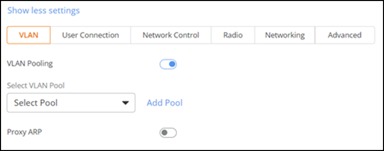
Configuring the VLAN Settings for a Wi-Fi Network
- Click the VLAN sub-tab.
- Toggle the VLAN Pooling switch on to assign a VLAN pooling policy to this WLAN.
- Select a VLAN pool from the Select VLAN Pooling
drop-down list.
If a VLAN pool is not yet defined, you can create a new one; click Add Pool, complete the fields in the Add VLAN Pool dialog box, and click Add. You can then select the newly created VLAN pool from the Select VLAN Pooling drop-down list. Refer to Creating a VLAN Pool for more information.
A VLAN pool policy allows a single VLAN, multiple VLANs (separated by commas), or a VLAN range (from 2 through 4094). By default, VLAN Pooling is disabled.
- Enter the VLAN ID number that you want to assign to this network.
- Enable Dynamic VLAN (enabled by default when MAC Authentication is enabled). Dynamic VLAN automatically and dynamically assigns wireless clients to different VLANs based on their MAC addresses, using either a pre‑registered MAC list or an external MAC authentication service.
- Toggle the Proxy ARP switch on to enable this network to respond to ARP requests. Proxy ARP is disabled by default.
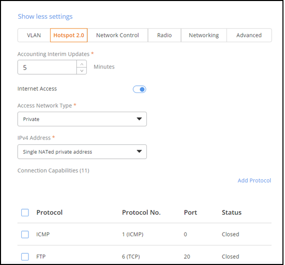
Configuring the Hotspot 2.0 Settings for a Wi-Fi Network
- Select the Hotspot 2.0 sub-tab.
- Set the Accounting Interim Updates interval, ranging from 0 to 1440. The default value is 5 minutes.
- Internet Access is enabled by default, allowing devices to connect to the internet through the hotspot. Toggle the Internet Access switch off to disable this option. When disabled, any device attempting to connect to the Hotspot Wi‑Fi network can connect to the network but cannot access the internet.
- Select the Access Network Type from the drop-down list.
- Select the IPv4 Address for the network from the drop-down list.
- Select a preconfigured
protocol from the Connection Capabilities.If a protocol is not yet defined, you can create a new one; click Add Protocol.An Add Protocol sidebar is displayed. Complete the following to add a protocol:
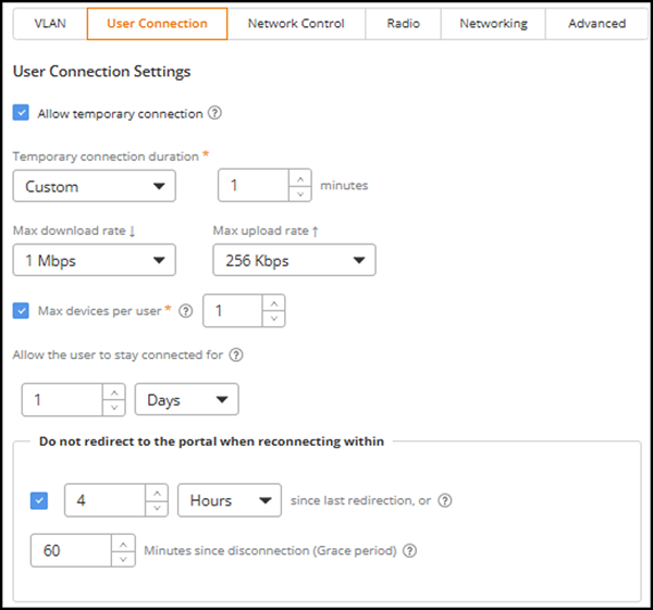
Configuring the User Connection Settings for a Wi-Fi Network
- Select the User Connection sub-tab.
- Allow temporary
connection: Select the Allow temporary
connection checkbox to enable temporary, limited internet
access for guests after they request a one‑time password (OTP). This access
allows guests to retrieve verification codes through SMS, email, or
WhatsApp, even when mobile data is unavailable.Note: The Allow temporary connection option is available only when the portal type is Self Sign‑In and at least one of the following sign‑in methods is enabled: SMS Token, Email, or WhatsApp. This option does not appear for other onboarding methods.Note: During the temporary connection period, users are not automatically redirected to the captive portal, so they may be unable to sign in immediately using the passcode sent to them. The captive portal URL is included only when users authenticate via email, enabling them to access the portal proactively.
When enabled, the following additional fields appear:
-
Temporary
connection duration: Select the duration for which
temporary internet access remains available after the user requests
a verification code. The options are 1,
2, 5
(default), 10,
and 15
minutes, or choose Custom to manually enter a duration within the
allowed range.
When Custom is selected, enter the number of minutes in the numeric field. The allowed range for custom values is 1–15 minutes.
- Max download rate: Select the download bandwidth limit during the temporary access period. The options are 1 Mbps (default), 2 Mbps, 5 Mbps, and Unlimited.
- Max upload rate: Select the upload bandwidth limit during the temporary access period. Options include: 256 Kbps (default), 512 Kbps, 1 Mbps, and Unlimited.
ACX-105622 -
Temporary
connection duration: Select the duration for which
temporary internet access remains available after the user requests
a verification code. The options are 1,
2, 5
(default), 10,
and 15
minutes, or choose Custom to manually enter a duration within the
allowed range.
- Max devices per
user:
- Select the Max devices per
user checkbox to limit the maximum number of devices
a guest can connect using a single credential.
Enter a value ranging from 1–1,000. You can enter a value directly or adjust it using the spinner. The default value is 1.
- Clear the Max devices per user checkbox to allow unlimited devices.
Note: This setting is supported only for the following Captive Portal guest network types: Self Sign-In, Host Approval, Active Directory LDAP Server, and SAML Identity Provider (IdP).ACX-98973 - Increase the limit of "maximum number of devices per credentials" for SMS/WhatsApp - Select the Max devices per
user checkbox to limit the maximum number of devices
a guest can connect using a single credential.
- Allow the user to stay
connected for: Select Minutes,
Hours, or Days from the
drop-down list, and then enter the connection duration after which the
client is disconnected. By default, the duration is set to 1 day. The valid
range is 2–14,400 minutes, 1–240 hours, or 1–10 days, depending on the
selected time unit.Note: After exceeding the configured session duration, the client is disconnected from the network and prompted to re-authenticate with the portal.
- Do not redirect to the
portal when reconnecting within:
- Select the Do not redirect to the portal when reconnecting within checkbox to enable this setting. When enabled, select Minutes, Hours, Days, or Weeks from the drop-down list, and then enter the duration. This setting defines the wait time after which the client is redirected to the portal for re-authentication. The valid range is 1–1,440 minutes, 1–24 hours, 1–30 days, or 1–7 weeks, depending on the selected time unit.
- Clear the Do not redirect to the portal when reconnecting within checkbox to disable this setting. When disabled, clients are redirected to the portal whenever they reconnect.
- You can set the Grace Period, which determines the number of minutes during which previously authenticated clients can reconnect to the network without re-authentication. By default, the grace period is set to 60 minutes. However, the grace period cannot exceed the total connection time allotted to the user or 14,399 minutes (approximately 10 days).
Configuring the Network Control Settings for a Wi-Fi Network
- Select the Network Control sub-tab.
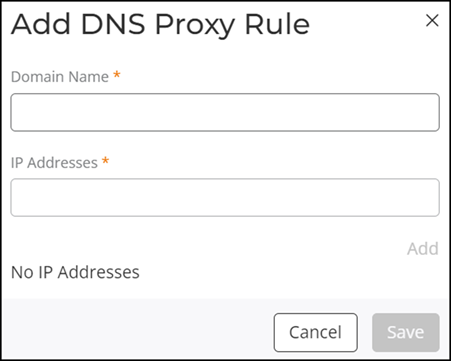
- (Optional) Toggle the DNS Proxy switch on. The DNS Proxy dialog box is displayed. DNS Proxy enables this network to respond to DNS requests. DNS Proxy is disabled by default.
- (Optional) Toggle the
Wi-Fi
Calling switch on to allow voice calls over a Wi-Fi network
instead of a cellular network. Wi-Fi Calling
is disabled by default.
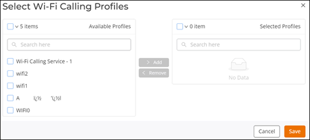
- Toggle the Select Profiles switch on. The Select Wi-Fi Calling Profiles dialog box is displayed.
- Select the profiles in the Available Profiles table and click Add to move the selected profile to the Selected Profiles table. To remove the profiles from the Selected Profiles table, select the profiles in the Selected Profiles table and click Remove.
- Click Save.
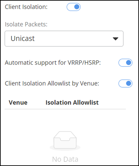
- (Optional) Toggle the
Client
Isolation switch on to prevent devices on the same network
from communicating directly with each other, enhancing security. Client
Isolation is disabled by default.
- Isolation Packets: Select Unicast, Multicast/broadcast, or Unicast and Multicast/broadcast from the drop-down list.
- Automatic support for VRRP/HSRP: Set the switch on to enable automatic support for VRRP/HSRP.
- Client Isolation Allowlist by Venue: Set the switch on to enable the client isolation allowlist by venue.
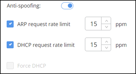
- (Optional) Toggle the Anti-spoofing switch on to verify the authenticity of devices and prevent IP address spoofing. Anti-spoofing is disabled by default.
- (Optional) Toggle the Logging client data to external syslog switch on to send client activity logs to an external Syslog server for monitoring and analysis. Logging client data to external syslog is disabled by default.
- (Optional) Application Recognition
& Control is enabled by default. This setting manages
the usage and reporting of network guest application activities. You can see
the application usage of device clients from the RUCKUS One
dashboard. Disabling this setting stops the monitoring and reporting of
these activities.
ACX-67980
- (Optional) Under DHCP,
configure the following settings:
- Force DHCP: Ensures that all devices on this network obtain their IP addresses through the DHCP server. Force DHCP is disabled by default. Toggle the Force DHCP switch on to enable this setting. If you enable the Anti-spoofing setting, then Force DHCP is disabled and grayed out.
- DHCP Option
82: DHCP Option 82 allows a DHCP relay agent to
insert circuit-specific information (such as port or MAC address)
into DHCP packets before forwarding them to the DHCP server. This
enables the server to assign IP addresses based on client location
or relay source. In RUCKUS One,
this feature is supported for wireless clients and for wired clients
connected via AP LAN ports. By default, this feature is disabled.
Toggle the DHCP Option 82 switch on to enable this feature.
After enabling DHCP Option
82, configure at least one of the following
sub-options:
- Agent Circuit ID (#1): Click the toggle to enable this option, then select how the AP interface or port is identified from the drop-down list.
- Agent Remote ID (#2): Click the toggle to enable this option, then select the identifier for the AP forwarding the DHCP request from the drop-down list.
- DHCPv4 Virtual Subnet Selection (#150): Click the toggle to enable or disable this setting to define whether a virtual subnet should be used for IP address assignment.
- DHCPv4 Virtual Subnet Selection Control (#151): Click the toggle to enable this option, then select and configure how the virtual subnet is applied. Options include Area and ESSID. If you select Area, a text field appears where you can enter the area name (1 to 26 characters).
- AP and Client MAC Format Delimiter: Choose the syntax used to format MAC addresses. Options include AA:BB:CC:DD:EE:FF (the default), AA-BB-CC-DD-EE-FF, and AABBCCDDEEFF.
- (Optional) Toggle the
Access
Control switch on to enable assignment of access control
policies to the network.
- Select a policy from
the Access
Control Policy drop-down list.If a policy is not yet defined, you can create a new one; click Add, complete the fields in the Add Access Control Policy sidebar, and click Add. You can then select the newly created profile from the drop-down. For more information, refer to Creating an Access Control Policy.
- (Optional) Click Select Separate Profiles to select an access control policy.
- Select a policy from
the Access
Control Policy drop-down list.
Configuring the Wi-Fi Radio Settings for a Wi-Fi Network
- Select the Radio sub-tab.ACX-114121
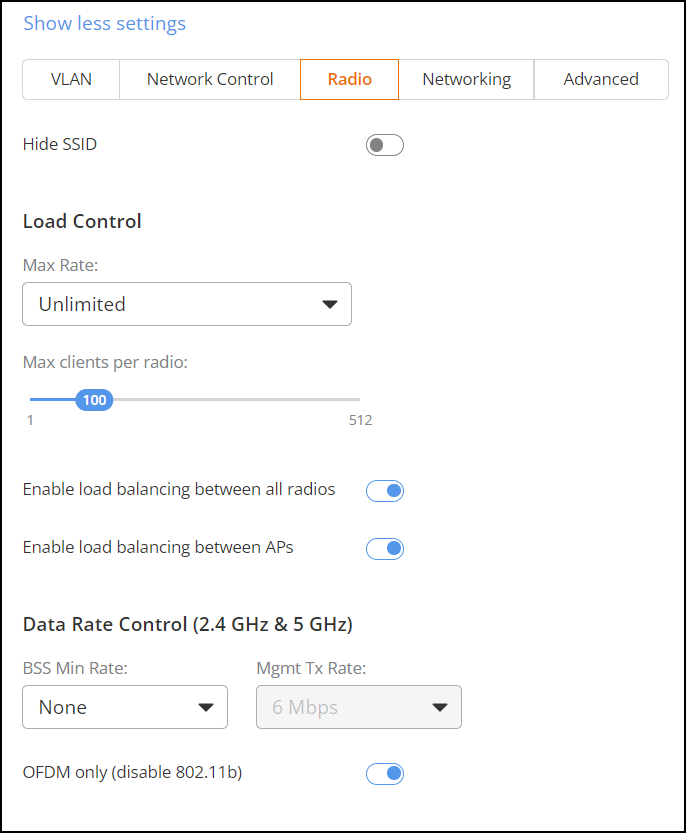
- Toggle the Hide SSID switch on if you want to hide the network name from being broadcast. This setting is disabled by default.
- Under Load
Control, complete the following fields:
- Max Rate: Choose one of the following
options from the drop-down list:
- Unlimited (default): No limits on bandwidth allocation.
- Per AP: The maximum bandwidth allocation limit of all connections to that specific network on the AP. If selected, two other options appear (enabled by default), Upload Limit and Download Limit. If either (or both) checkboxes are selected, a sliding scale appears and you can drag your cursor along the line to choose the Mbps limits for each. The upload and download limit ranges from 1 through 500 Mbps.
- Max clients per radio: Limits the number of clients that can associate with this network per AP radio (default is 100). The value ranges from 1 through 512.
- Band Balancing (disabled for DPSK3 networks): Toggle the switch on to distribute client load between radios. Ensure Band Balancing is also enabled at the venue level in . For DPSK networks that use WPA2/WPA3 mixed mode (DPSK3), this option is automatically disabled to prevent client connectivity issues.
- Load
Balancing (enabled by default): Toggle the switch on
to distribute client load across access points so that no single AP
is overloaded. Ensure Load
Balancing is also enabled at the venue level in
.
ACX-114121
- Max Rate: Choose one of the following
options from the drop-down list:
- Under Data Rate Control (2.4 GHz & 5 GHz),
configure the following settings:
- BSS Min Rate: Select None, 1 Mbps, 2 Mbps, 5.5 Mbps, 12 Mbps, or 24 Mbps from the drop-down list. Use the BSS Min Rate option to configure the minimum transmission rate that is supported by the network. If OFDM Only (Disables 802.11b) is enabled, the only valid options are 12 Mbps and 24 Mbps, with Mgmt Tx Rate fixed at 6 Mbps. This option can also be used to prevent 802.11b clients from connecting, and to allow greater client density with higher data rates.
- Mgmt Tx Rate: Select 1, 2, 5.5, 6, 9, 11, 12, or 18 Mbps from the drop-down list. This option is only available if OFDM only (Disables 802.11b) is disabled, and BSS Min Rate is set to None. (Otherwise, the Mgmt Tx Rate is defined by those settings.) Use the Mgmt Tx Rate setting to configure the rate at which management frames are sent. The default is 6 Mbps.
- OFDM only (Disables 802.11b): Toggle the switch on to disable CCK rates of 1, 2, 5.5, and 11 Mbps so that 802.11b-only clients cannot connect. The system transmits beacons and probe responses at 6 Mbps and transmits data frames at 6, 9, 18, 24, 36, 48, and 54 Mbps. Higher minimum data rates improve overall network throughput but reduce the distance at which clients can remain connected. This option is disabled by default.
Defect ID - ACX-100002
Configuring the Networking Settings for a Wi-Fi Network
- Select the Networking sub-tab.
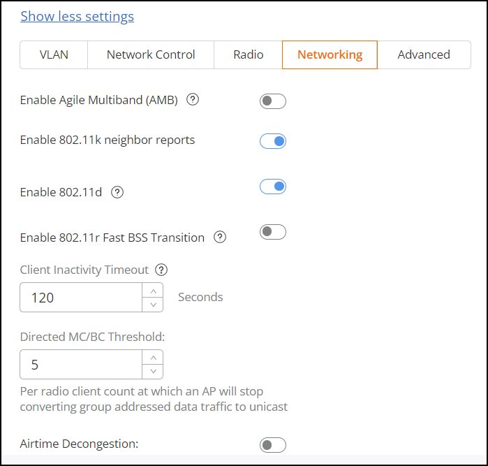
- Toggle the Enable Agile Multiband
(AMB) switch on to enable the feature. This setting is
disabled by default. Enabling AMB configures the WLAN to send a Multi‑Band Operation announcement that helps guide client roaming decisions. Other roaming‑related features, including 802.11k, 802.11r, and 802.11w, must be enabled or disabled separately.
- Toggle the Enable 802.11k neighbor reports switch on to enable the feature. This setting provides a list of nearby APs to help clients make faster roaming decisions. This setting is enabled by default.
- Toggle the Enable 802.11d switch on to enable the feature. This setting adds country information to beacons and probe messages so the AP can operate correctly across different regulatory domains. This setting is enabled by default.
- Toggle the Enable 802.11r Fast BSS Transition switch
on to enable the feature, and set a Mobility Domain ID (valid range:
1 through 65535). This setting is disabled by default.
When enabled, 802.11r Fast BSS Transition improves the efficiency of handoff processes between access points (APs) within the same network. This feature reduces the time required for a client device to authenticate with a new AP, ensuring smoother transitions and maintaining continuous connectivity.
Mobility Domain ID defines the network area for fast roaming in IEEE 802.11r, allowing shared master keys for seamless client transitions.
Over-the-Distribution System (DS) support in the IEEE 802.11r Fast Basic Service Set (BSS) Transition protocol can significantly enhance the efficiency of Fast Transition (FT) support. This feature allows a client device to pre-authenticate with a target Access Point (AP) through the currently connected AP. As a result, when the client device roams, it can complete the transition with a simple re-association handshake, ensuring a smoother and quicker handover process.
Roaming Improvement feature - Liu Scott SME inputs - For Client Inactivity Timeout, set the duration of inactivity (in seconds) after which a client is disconnected from the network. The valid range is from 60 through 86,400 seconds.
- For Directed MC/BC Threshold, set the threshold for converting multicast or broadcast traffic to unicast to improve network efficiency. The valid range is from 0 through 5.
- The Airtime Decongestion setting optimizes airtime usage by ensuring that all devices connected to the Wi-Fi network get a fair share of the available bandwidth. This setting is enabled by default.
- For Join RSSI Threshold, disable Airtime Decongestion to enable Join RSSI Threshold setting. Toggle the Join RSSI Threshold switch on (default is -80 dBm) and set the minimum signal strength (must be between -90 and -60 dBm) required for a client to join the network. By default, Join RSSI Threshold is disabled.
- Toggle the
Transient Client Management switch on and configure
the following parameters:
Transient Client Management manages clients that frequently connect and disconnect to maintain network stability. This setting is disabled by default.
- Join Wait Time: Enter a value in seconds or use the arrows. Valid value ranges from 1 through 60 seconds. The default value is -1.
- Join Expire Time: Enter a value in seconds or use the arrows. Valid value ranges from 1 through 300 seconds. The default value is -1.
- Join Wait Threshold: Enter a value in seconds or use the arrows. Valid value ranges from 1 through 50 seconds. The default value is 10 seconds.
- Toggle the Optimized Connectivity Experience (OCE) switch on and configure the following parameters:
- Toggle the AP Host Name Advertisement in Beacon switch on to advertise the hostname of an AP in beacon frames for easier identification. This setting is disabled by default.
- The GTK Rekey setting allows periodic generation of a new group key for securing multicast or broadcast traffic. This setting is enabled by default.
- Toggle the
Multicast Filter switch on to enable this feature.
By default, Multicast Filter is disabled. Multicast Filter filters multicast traffic to reduce unnecessary network load. When the Multicast Filter option is enabled on an AP, it drops all IPv4 and IPv6 multicast and broadcast traffic from associated wireless clients except for the following, which forms the "multicast filter bypass" list. Note that the downstream multicast is unaffected.
- Multicast Rate
Limiting limits the rate of multicast traffic to prevent
network congestion. Multicast
Filter must be enabled to configure the Multicast Rate
Limiting setting.
Multicast Filter and Multicast Rate Limiting are mutually exclusive features. From the RUCKUS One web interface, you cannot enable them at the same time. SSID rate limiting will always take precedence if Multicast rate limiting is also configured. Multicast downlink rate limiting should not be greater than 50% of BSS min rate.
- BSS Priority: Adjusts the priority of Basic Service Set (BSS) to manage traffic more effectively. Set the BSS Priority to Low or High.
- Under Wi-Fi
7, configure the following settings:
- Enable Wi-Fi 6/ 7: Allows some legacy Wi-Fi 5 clients with out-of-date drivers to interoperate with a Wi-Fi 6/7 AP. Toggle the Enable Wi-Fi 6/ 7 switch on. By default, Enable Wi-Fi 6/ 7 is enabled.
- Enable Multi-Link
operation (MLO): Toggle the switch on to enable the
MLO feature. When you enable this feature, all three bands, 2.4 GHz,
5 GHz, and 6 GHz, are selected by default.
MLO allows Wi-Fi 7 devices to use multiple radio channels simultaneously (at least two) for better throughput and efficiency. For MLO to function, radios on APs must be active, and their usage is determined by AP configuration, which limits the number of supported 6 GHz networks.
Note: For DPSK networks, this feature is not supported and this toggle is inactive.
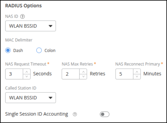
- Under RADIUS
Options, configure the following settings. This option is
available for Enterprise AAA (802.1X), Hotspot 2.0 Access, Open Network with
External MAC Authentication, and third-party captive portal network
types.
- NAS ID: Identifies clients to a RADIUS server. Select an option from the list.
- MAC Delimiter: Select Dash or Colon.
- NAS Request Timeout: Enter the timeout period (in seconds) after which an expected RADIUS response message is considered to have failed.
- NAS Max Retries: Enter the number of failed connection attempts after which RUCKUS One will failover to the backup RADIUS server.
- NAS Reconnect Primary: Enter the number of minutes after which RUCKUS One will attempt to reconnect to the primary RADIUS server after failover to the backup server.
- Called Station ID: Allows NAS to send the ID that is called by the user. Select an option from the list.
- Single Session ID
Accounting: Allows the APs to maintain one
accounting session (including statistics) for a user roaming between
APs. This setting is disabled by default. Toggle the switch on to
enable the feature.
This option is not visible unless one of the selected identity providers enables an accounting service. You can find the Accounting Service option in the AAA Settings page by navigating to .
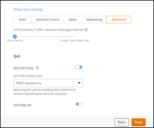
Configuring the Advanced Settings for a Wi-Fi Network
- Select the Advanced sub-tab.
- Set the DTIM
(Delivery Traffic Indication Message) Interval to a value
ranging from 1 (default) through 255.The DTIM interval controls how often DTIM messages are transmitted, and this affects the frequency of data transmissions per broadcast beacon. Setting the DTIM interval to a lower value results in more frequent DTIM messages, which can prevent mobile devices from going into power‑save mode and thereby increase battery consumption.
-
Doc defect - ACX-82790. Inputs from Chandan Sreshta and Andre Rosete.Toggle the QoS Mirroring switch to disable or enable the feature. QoS Mirroring is enabled by default. QoS Mirroring enables APs to learn User Priority (UP) from uplink traffic and mirror it in downlink traffic. This ensures proper traffic differentiation, prioritizing critical applications like voice and video to maintain QoS. By default, QoS Mirroring is enabled. Configure the QoS Mirroring Scope by selecting one of the following options from the drop-down list:
- MSCS requests only (default): When selected, QoS Mirroring is enabled only for clients that send mirrored stream classification service (MSCS) requests.
- All clients: When selected, QoS Mirroring is enabled for all clients.
Click the
 icon next to QoS
Mirroring to view the feature synopsis and the minimum
required AP firmware version. Click See the compatibility
requirements to view the minimum required AP firmware
version and the supported AP model families (denoted by their applicable
IEEE 802.11 standard).
icon next to QoS
Mirroring to view the feature synopsis and the minimum
required AP firmware version. Click See the compatibility
requirements to view the minimum required AP firmware
version and the supported AP model families (denoted by their applicable
IEEE 802.11 standard). - Toggle the QoS Map Set switch on. The QoS Map Set setting reprioritizes downlink packets based on the configured mappings. When an AP receives a downlink packet, it checks the existing DSCP (Layer 3 QoS) marking, compares it to this map set and then changes the user priority (Layer 2 QoS) values for transmission by the AP. By default, QoS Map Set is disabled.
- Click Next to go to the Venue page to activate this network on the venue.