Multi-venue Support
- On the RUCKUS One navigation bar, select .
- Find the SD-LAN
tile and click Add.
This displays the Add SD-LAN Service page.
- In the Add SD-LAN Service page, configure the following:
- Click Next.
The Wi-Fi Network Selection page is displayed.
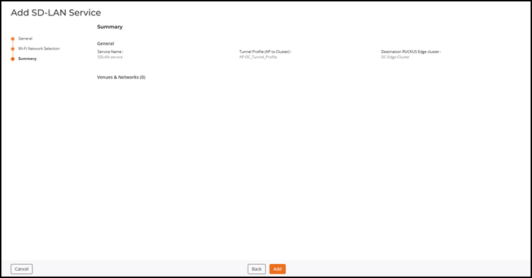
- Click Next. The Summary page is displayed.
- Review the settings and click Add.
The SD-LAN service is configured with an AP to Cluster tunnel profile and the service is applied to the selected Wi-Fi network.
Adding SD-LAN Service Without Venues or WLANs
An SD‑LAN service can be created without selecting any venues or WLANs. You can add venue WLANs later as required.
To configure SD-LANs without venues or WLANs:
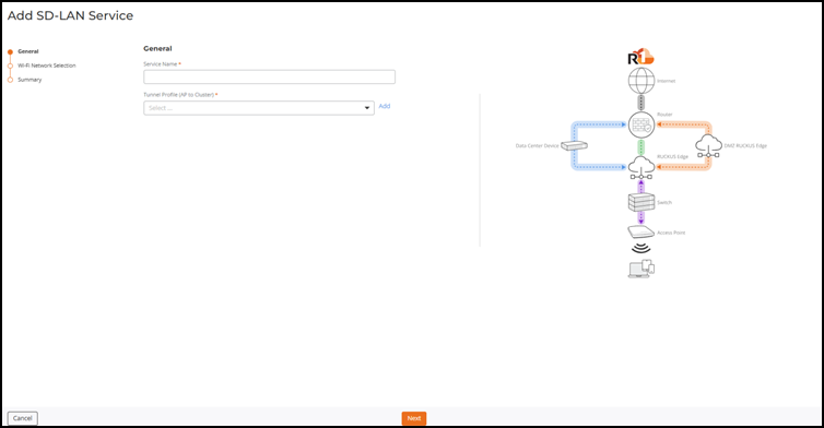
- On the RUCKUS One navigation bar, select .
- Find the
SD-LAN tile and click Add.
This displays the Add SD-LAN Service page.
- In the Add SD-LAN Service page, configure the following:
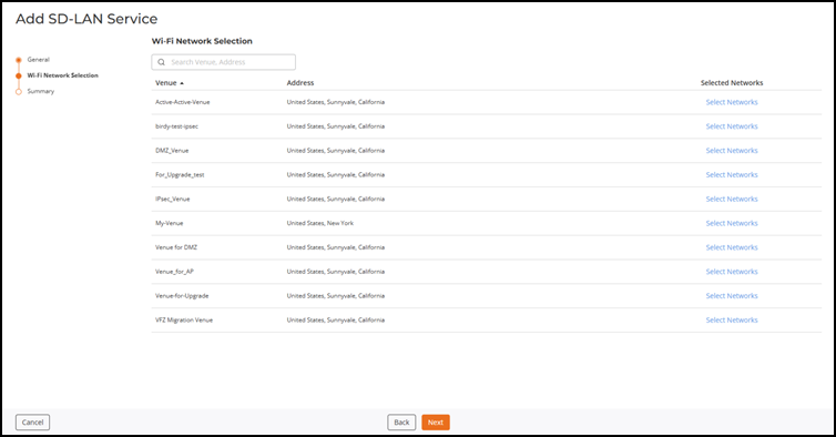
- Click Next.
The Wi-Fi Network Selection page is displayed.
- Click Next. The Summary page is
displayed.
The SD‑LAN service is created with zero venues and zero APs.
- Review the settings and click Add.
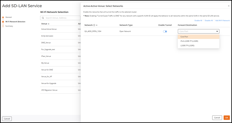
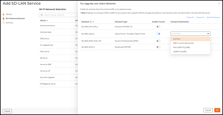
Forward Destination Selection
With the SD‑LAN service, client traffic can be forwarded to either the data center (DC) core network or an L2GRE destination. Only guest client traffic is forwarded to the DMZ Edge cluster over a VxLAN tunnel.
Select one of the following Forward Destination options:
- Core Port: For forwarding client traffic to the DC core network.
- L2GRE Tunnel Profile: For forwarding client traffic to an L2GRE tunnel endpoint.
- DMZ Tunnel Profile:
For forwarding guest client traffic to a DMZ Edge cluster.
Note: Use a unique VLAN for each WLAN that requires a different SD-LAN forwarding destination. The Edge device forwards traffic on a per-VLAN basis, and the first active WLAN associated with a VLAN establishes the forwarding path for all WLANs using that VLAN. Do not enable VLAN pooling on these WLANs.
SD-LAN service with selected Venues or WLANs
This section outlines the process for configuring forward destinations for client traffic as part of the SD‑LAN service setup.
To complete the configuration:
- From the Select Networks sidebar, toggle Enable Tunnel.
- Select the required Forward Destination for the active network.
- Click OK, and then click Next.
- Review the configuration and
click Add.
The SD‑LAN service is configured using the selected AP‑to‑cluster tunnel profile and applied to the chosen Wi‑Fi networks.