Configuring a Cluster for Active Standby High Availability Deployment with a LAG Interface
- Log in to the RUCKUS One web user interface with your credentials.
- On the RUCKUS One navigation
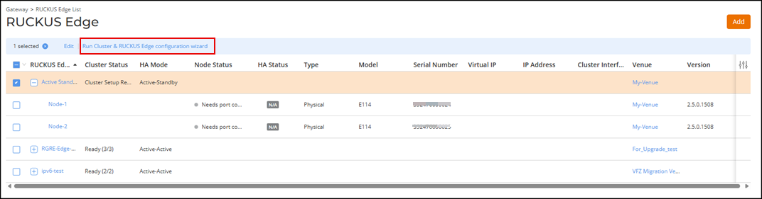
bar, click .This displays the RUCKUS Edge page.
- Select the checkbox adjacent to the RUCKUS Edge cluster. This highlights the Edit and Run Cluster & RUCKUS Edge configuration wizard options.
- Click the Run Cluster & RUCKUS Edge configuration wizard option.
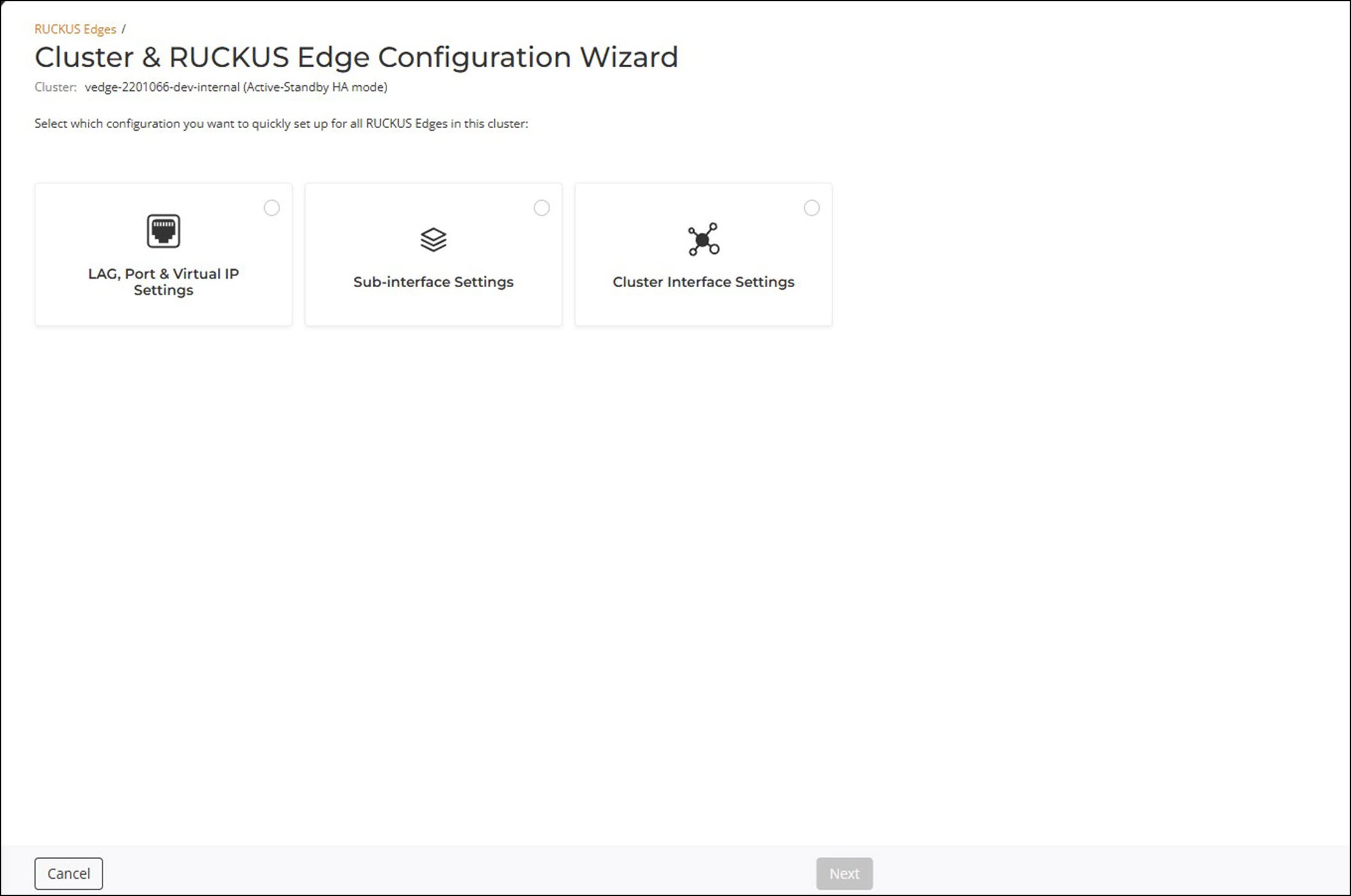
- Select the LAG, Port & Virtual IP Setting checkbox and click Next to start the configuration.
- Proceed to section Link Aggregation Group (LAG), Port and Virtual IP Settings for configuration details.
Link Aggregation Group (LAG), Port and Virtual IP Settings
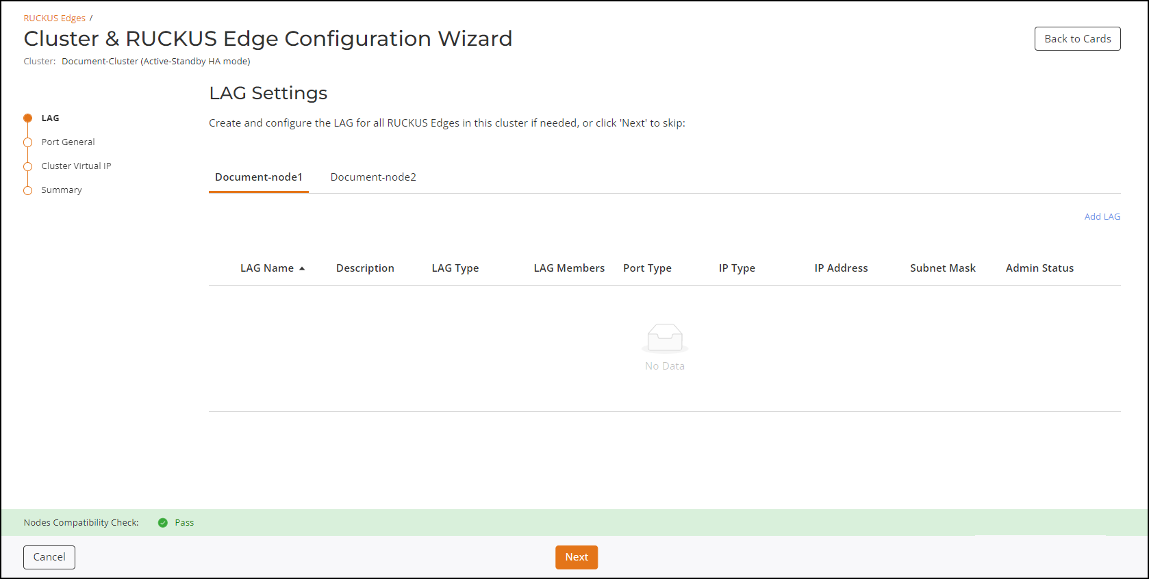
- LAG Settings: Click the Add LAG option.
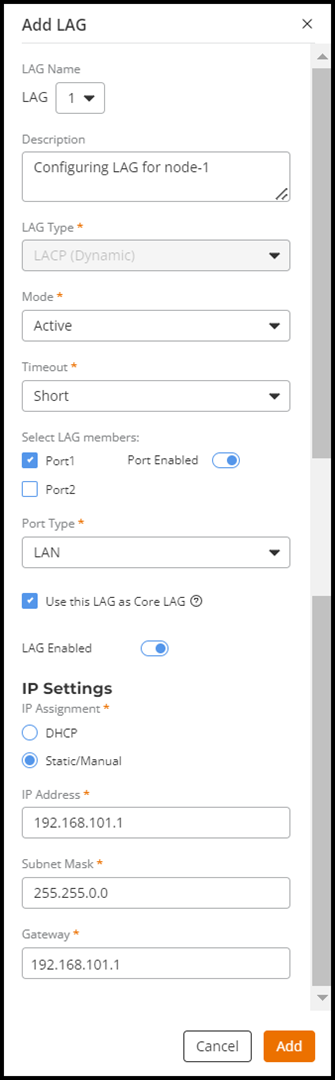
- On the Add LAG interactive sidebar, complete the
fields and click Add.Note: Refer to Configuring Link Aggregation Group for descriptions of the fields in the Add LAG sidebar.
- Repeat and for the second node. When the compatibility check
successfully passes, click Next to proceed to the next page of the
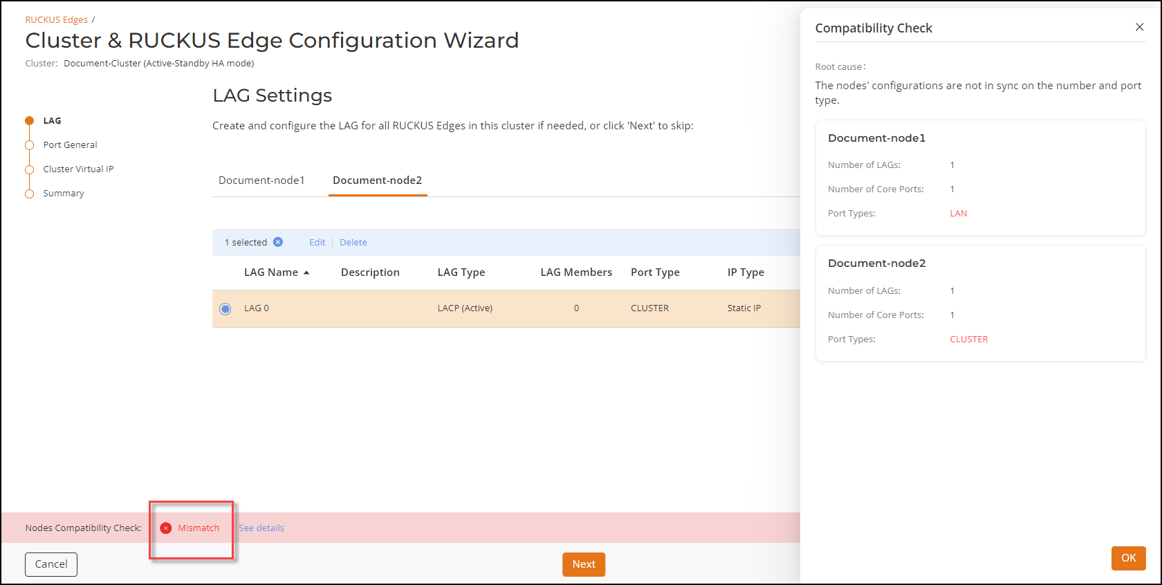
wizard.RUCKUS One performs a compatibility check of the configurations on each node. If a mismatch is detected, it displays a warning message labeled Mismatch. You can click on the See Details option to view the root cause and specifics of the mismatch to quickly identify the discrepancies.
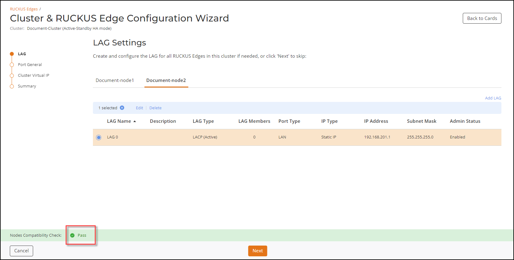
You can Edit or Delete the offending LAG by selecting the checkbox adjacent to the LAG. After the mismatches are resolved, the compatibility check result changes to Pass.
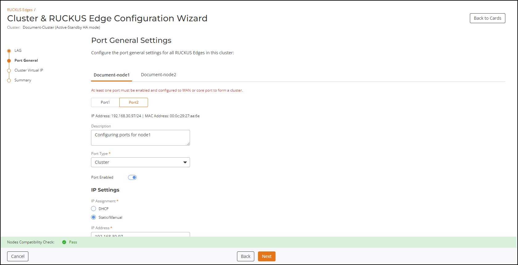
- Ports General
Settings: Configure the port general settings for all Edge
devices.
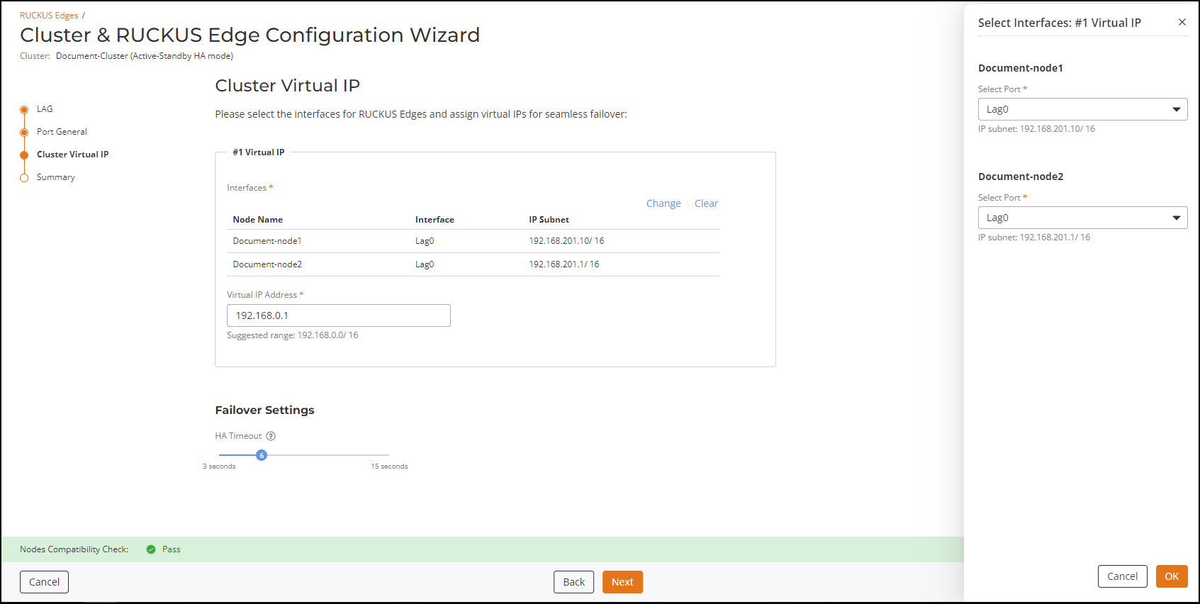
- Cluster Virtual
IP: Virtual IP Address of a Cluster is similar to any other
IP address except it does not have a specific host or node to resolve.
- Virtual IP: In this section, click Select Interface link. This displays the Select Interfaces sidebar. In the Select Interfaces window, select the Ports for node 1 and 2 and click Ok. The Node Name, Interface and IP address details are displayed in the Virtual IP section.
- Virtual IP Address: Enter the VRRP IP address for switches to connect to Edge.
- Failover Settings: Drag the HA
Timeout timeline bar to adjust the amount of time
allowed to elapse before triggering a failover.
Note: An HA failover time of 6 seconds or longer is recommended for Edge use-cases. A timer set to less than this is very aggressive and could potentially cause VRRP issues in some networks. HA timeout refers to the time period within which a node must receive a periodic heartbeat signal from the active node. If the timer expires prior to receiving a heartbeat signal, then the system initiates the failover process to select the next active node and maintain system functionality.
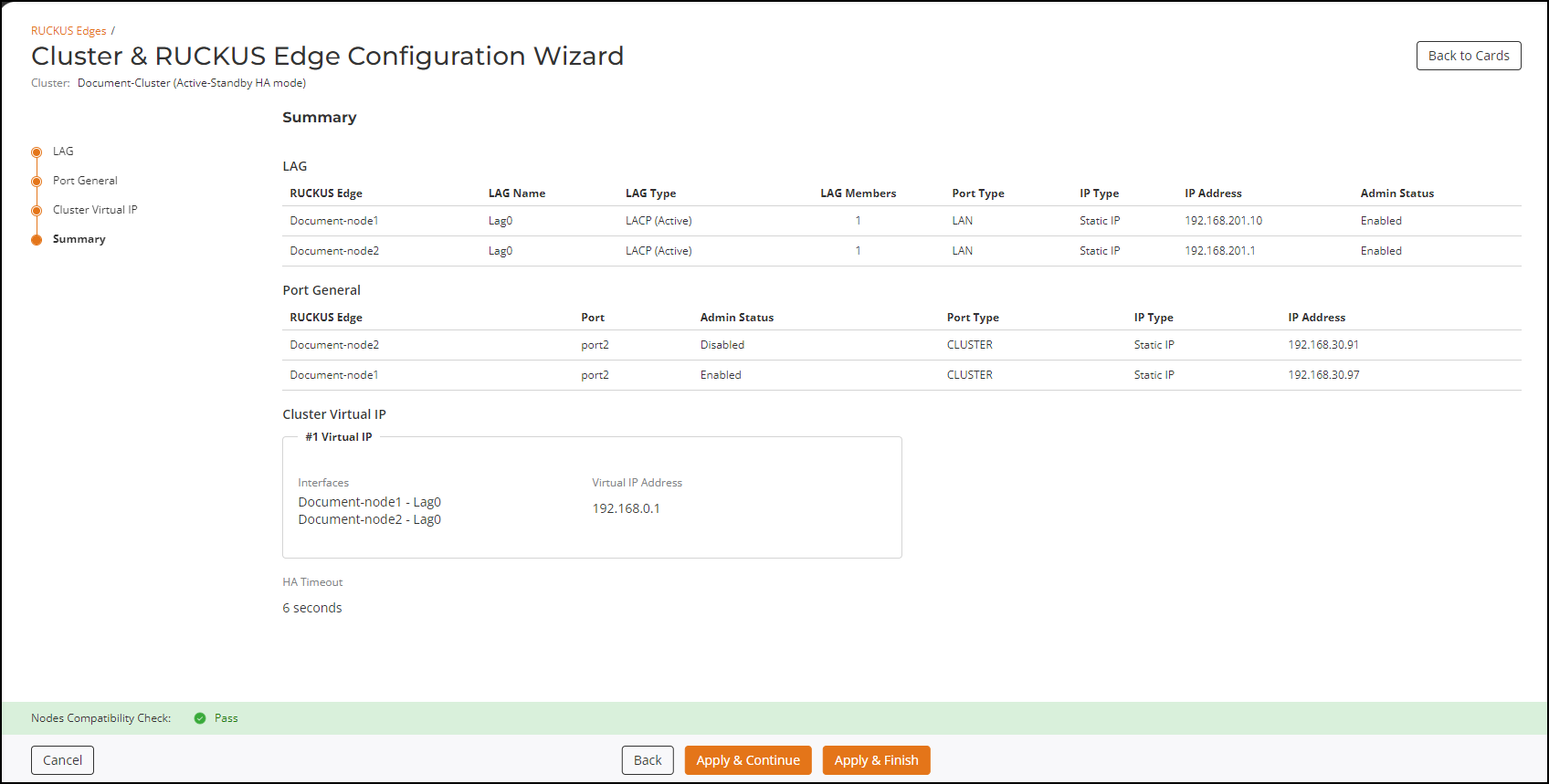
- Summary: This displays the configuration settings on the cluster. View and verify the configuration details and click Apply & Continue to proceed to the Cluster Interface Settings configuration, or Apply & Finish to complete the LAG, Port and Virtual IP Settings configuration without proceeding to the Cluster Interface Settings configuration.
- Proceed to section Cluster Interface Settings for configuration details
Cluster Interface Settings
After configuring the LAG, Port and Virtual IP Settings and clicking Apply & Continue (as described in Link Aggregation Group (LAG), Port and Virtual IP Settings), select the Cluster Interface checkbox and click Next. This displays Cluster Interface page containing a tab for each Edge device in the cluster.