R730

The R730 is the first Ruckus 802.11ax indoor Access Point. The R730 is a high-capacity, high-performance, eight-stream, dual-band 802.11ax AP with BeamFlex adaptive antenna technology for carriers and enterprises.

Front View Features

The following figure shows the top view of the R730. For a description of the front panel LEDs, refer to the table below.
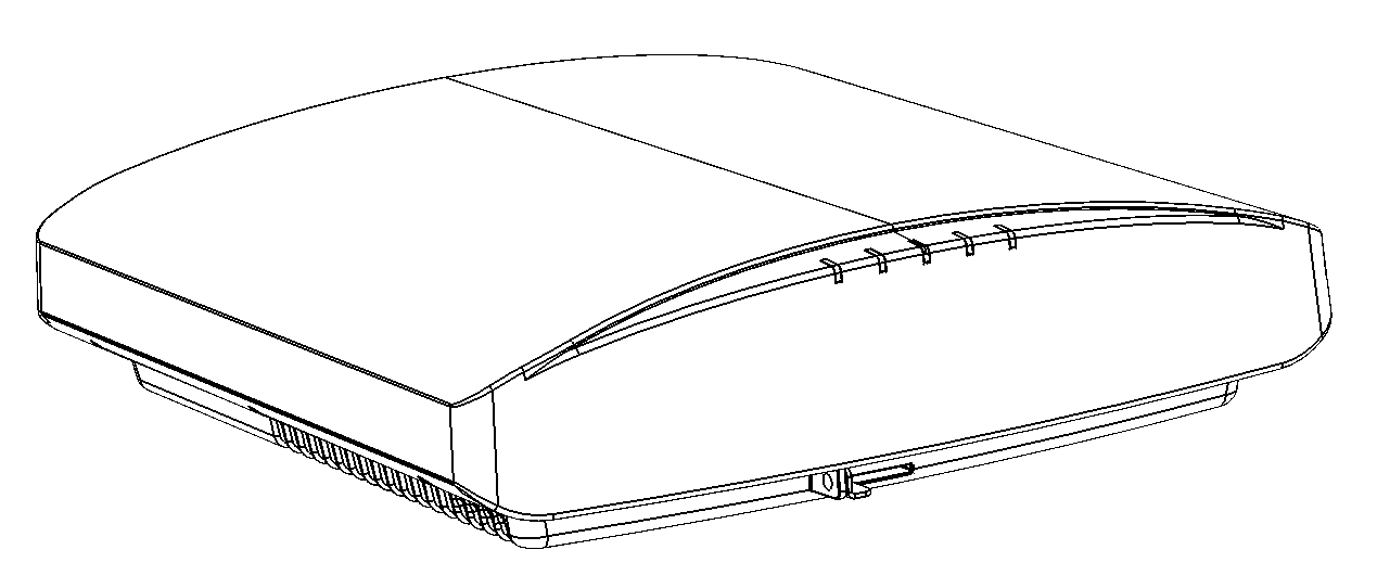
R730 front view

R730 front panel LEDs

LED Description
PWR
  • Off: Off.
  • Red: Boot up in process.
  • Flashing Green: No routable IP address
  • Green: On.
CTL
  • Off: The AP is not being managed by a Ruckus controller (standalone mode).
  • Green: The AP is being managed by a Ruckus controller.
  • Slow flashing green (one flash every two seconds): The AP is being managed by a Ruckus controller, but is currently unable to communicate with controller.
  • Fast flashing green (two flashes every second): The AP is being managed by a Ruckus controller and is currently receiving configuration settings (provisioning) or an image update.
AIR
  • Off: The AP is operating in standalone mode or operating as a root AP (RAP) or a non-mesh AP.
  • Green: The AP is functioning as a Mesh AP (MAP), and the wireless signal to its uplink AP is good.
  • Fast flashing green (two flashes every second): The AP is functioning as a Mesh AP (MAP), and the wireless signal to its uplink AP is fair.
  • Slow flashing green (one flash every two seconds): Mesh networking is enabled, but the AP is still searching for a mesh uplink.
2.4G
  • Off: The WLAN service is down.
  • Green: The WLAN is up and at least one client is associated.
  • Amber: The WLAN is up. No clients are associated.
5G
  • Off: The WLAN service is down.
  • Amber: The WLAN is up, but no clients or downlink MAPs are associated/connected.
  • Green: The WLAN is up and at least one client is associated. No downlink MAPs are connected.
  • Slow flashing green (one flash every two seconds): The WLAN is up and at least one downlink MAP is connected. No clients are associated.
  • Fast flashing green (two flashes every second): The WLAN is up, at least one downlink MAP is connected, and at least one client is associated.

Bottom Panel

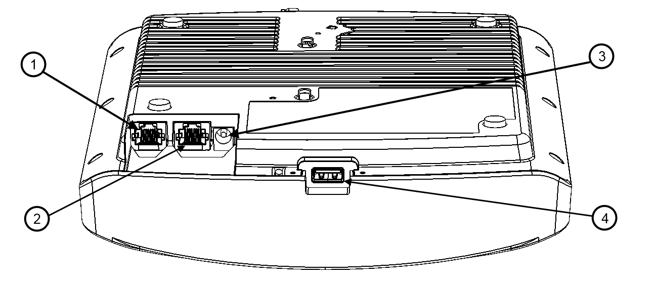
The bottom panel of the R730 includes the following:

  • 1000/2500/5000 Mbps PoE In Ethernet port
  • 10/100/1000 Mbps Ethernet port
  • 24V DC power socket
  • Reset button
  • USB port

R730 bottom panel

R730 Rear panel elements

No. Label Description
1 5G ETH PoE 100/1000/5000 Mbps PoE In Port: RJ-45 Ethernet port (supports 802.3at/at+ PoE in)
Note: If powered by 802.3at PoE, note that the feature set is reduced, as follows:
  • 4x4 (2.4GHz) + 4x4 (5GHz) chain operation mode (reduced from 4x4 (2.4GHz) 8x8 (5GHz) under full power)
  • LAN1 (10/100/1000 Mbps Ethernet port is disabled)
Note: The PoE switch port must run link layer discovery protocol (LLDP) power over Ethernet/MDI (PoE+) in order for the R730 to operate in full-power mode. This may require enabling both LLDP and Power via MDI (dot3) on the switch, if available.
Note: The recommended PoE injector for the R730 is GRT-480125A (60W power rating and 1 Gbps link speed). If using the recommended PoE injector, you must 1) manually select AT+ mode as the power mode in the SmartZone/ZoneDirector GUI, and 2) force 1Gbps link speed on the switch.
2 1G ETH 10/100/1000 Mbps port: RJ-45 Ethernet port (non-PoE)
3 48V 0.75A Connect a customer-ordered Ruckus DC power adapter (sold separately). When powered by the Ruckus power adapter, the AP supports a full feature set.
4 USB Port USB Port for IoT devices. Max Dimensions: 6 cm x 2 cm x 1.1 cm. Interface: USB 2.0. Connector: USB Type-A plug.

Ethernet Port LEDs

Behavior of Ethernet port LEDs on the R730

LED Description
Off Not connected
Amber + Green Connected to 5 Gbps device
Amber Connected to 2.5 Gbps device
Green Connected to 1000 Mbps device

R730 Power Modes

The following table lists the R730's power modes and the corresponding feature set under the different power modes. If both power sources are available, DC power will take priority and override PoE power.

When the AP is connected to a PoE switch, the max power requested by the AP is captured in the second column, and rest of the columns describe the operational capability for each mode.

Note: The dBm transmit power values below are per chain.

R730 Power Modes

PoE Mode

Power Level

5 GHz Radio

2.4 GHz Radio

5G Eth (PoE) Port

1G Eth Port

USB

160/ 80+80

802.3at 25.5 W 4 x 4

20 dBm

4 x 4

18 dBm

Enabled Disabled Enabled No
802.3at+ 35.0 W 8 x 8

20 dBm

8 x 8

18 dBm

Enabled Enabled Enabled Yes 2 x 2
Full Power (802.3bt, PoH, UPoE, 48VDC, injector) 35.0 W 4 x 4

22 dBm

4 x 4

23 dBm

Enabled Enabled Enabled Yes 2 x 2