R720
The R720 is a high-capacity, high-performance, four-stream, dual-band 802.11ac Wave
2 AP with adaptive antenna technology for carriers and enterprises.
Front View Features
The following figure shows the top view of the R720. For a description of the front panel LEDs, refer to the table below.
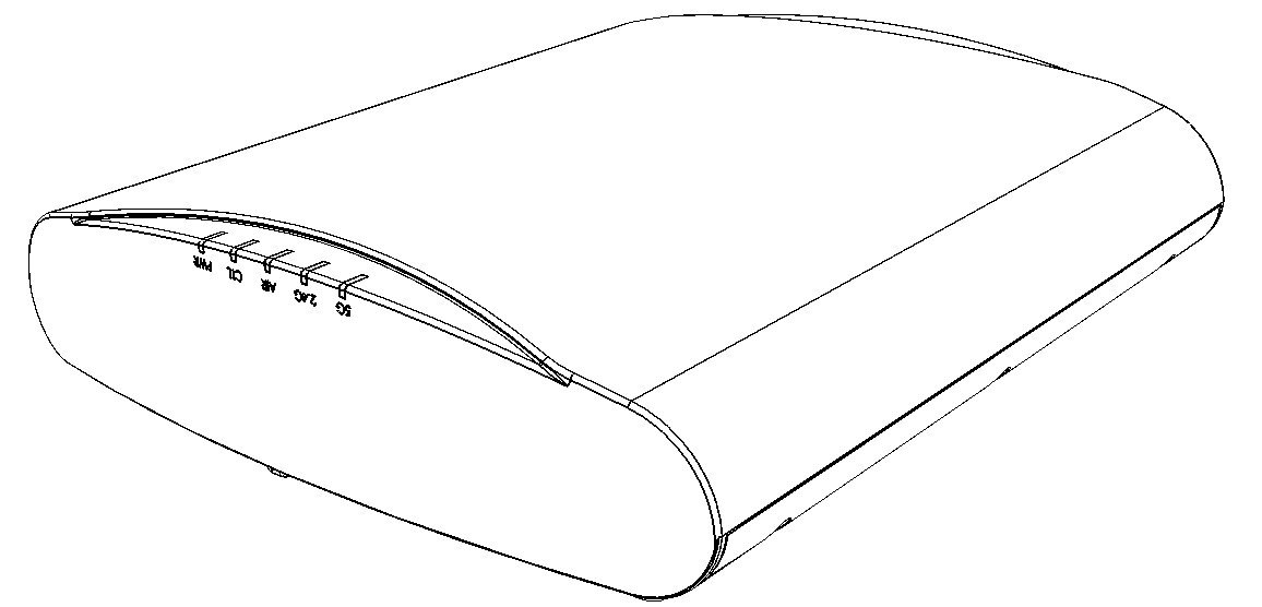
R720 front panel LEDs
Bottom Panel
The bottom panel of the R720 includes the following:
- one 100/1000/2500 PoE In Ethernet port
- one 10/100/1000 Ethernet port
- one 12VDC 2A power socket
- one reset button
- one USB port
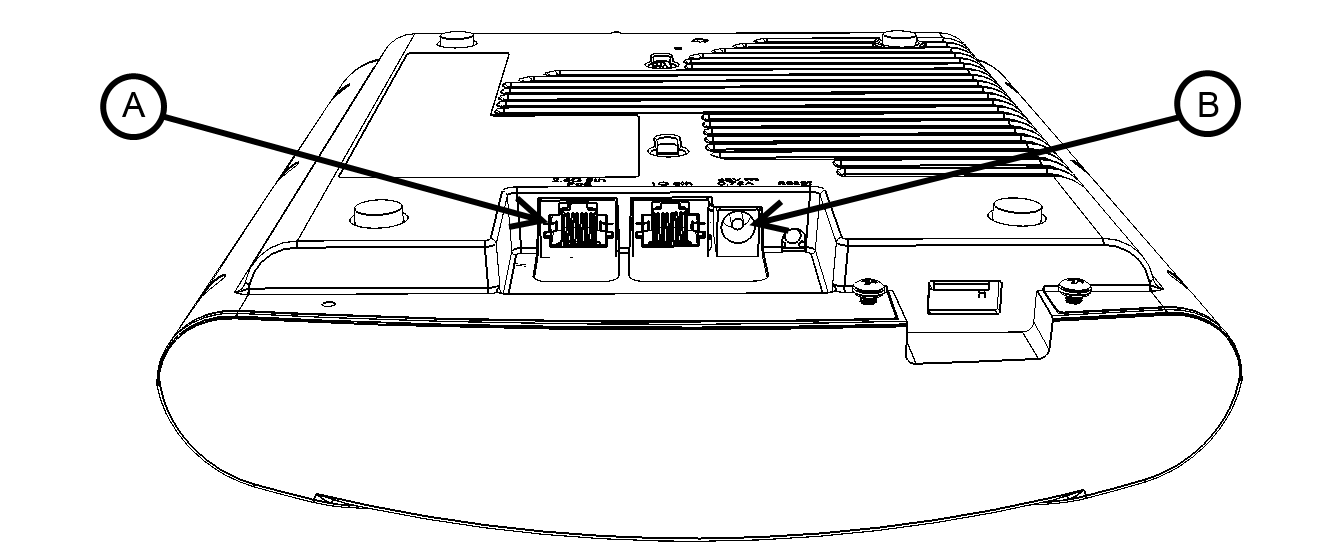
R720 Rear panel elements
| Label | Description |
|---|---|
| Ethernet (eth1) Port | RJ-45 port for a 10/100/1000 connection. |
| Ethernet + PoE (eth0) Port (A) | RJ-45 port for a 100/1000/2500 connection with 802.3af/802.3at-compatible PoE in support.
Note: The R720 can be powered by a 802.3at-compliant (25.5W) Power over Ethernet (PoE) switch
or PoE injector. --OR-- an 802.3af-compliant PoE switch or PoE injector.
Caution: The AP can operate off of 802.3af power, but the feature set is reduced, as follows:
1 x 4 radio chain operation mode, Second Ethernet port disabled, USB port disabled.
Note: The PoE switch port must run link layer discovery protocol (LLDP) power over Ethernet/MDI
(PoE+) in order for the R720 to operate in full-power mode. This may require enabling
both LLDP and Power via MDI (dot3) on the switch, if available.
|
| 48VDC Power Socket (B) | Connect a customer-ordered Ruckus Wireless AC power adapter (sold separately). When
powered by the Ruckus power adapter, the AP supports a full feature set.
Note: Power can alternately be supplied via the Ethernet + PoE port.
|
| RESET Button | Pressing, and then quickly releasing this internal button reboots the AP. Pressing
and holding it for six seconds resets the AP to factory default settings.
Note: Resetting the AP to factory default settings erases all settings that you configured
previously.
|
| USB Port | The R720 can have a low-power (0.5W or less) customer-supplied USB device plugged in. The USB device is hidden after the AP is attached to its mounting base. |
Ethernet Port LEDs
R720 Power Modes
The following table lists the R720's power modes and the corresponding feature set under the different power modes. When both power sources are available on an AP, then DC power will take priority and override PoE power. When the AP is connected to a PoE switch the max power requested by the AP is captured in the second column, and rest of the columns describe the operational capability for each mode.