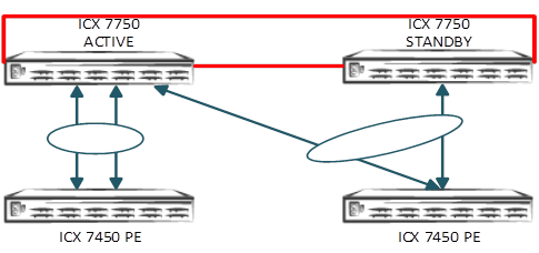
Topology 1: SPX-LAG Spanned Across the CB Stack Unit
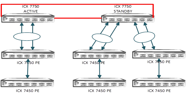
Topology 2: Multiple PE Chains Connected to the Same CB Unit
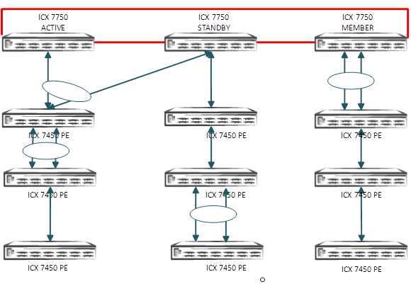
Topology 3: SPX-LAG Between PE Units
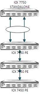
Topology 4: SPX with Standalone CB Unit
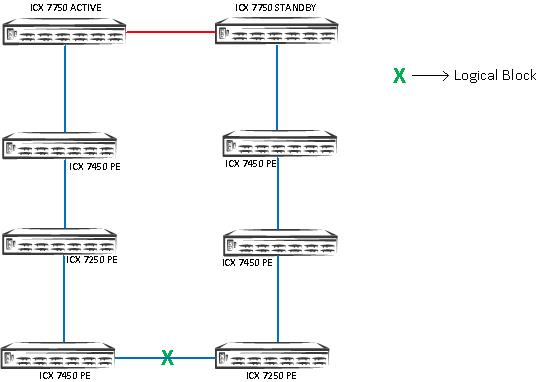
Topology 5: SPX PE Ring Topology from PE to CB Units
The green X indicates the location of the logical block for data flow through the
PE ring. The logical block is placed on the link that comes up last during the PE
ring formation.