The devices include LEDs that indicate the status of device components.
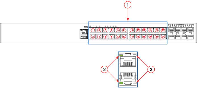
Note: The following figures show examples of the port status LEDs for similar ports are
present for models with a higher number of ports.
Port status LEDs on RJ-45 ports
RJ-45 ports
Status LEDs for corresponding ports
PoE/PoE+ LEDs for corresponding ports
Note: The PoE/PoE+ LEDs are reserved on models that do not support PoE or PoE+ operation.
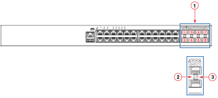
Port status LEDs for SFP or SFP+ ports
SFP or SFP+ ports
Bi-color status LED for upper port
Bi-color status LED for lower port
Port status LEDs
LED
Condition
Status
RJ-45 (1-24/48)
On/Flashing Green
The port has established a valid link at 10, 100, or 1000 Mbps. Flashing indicates
the port is transmitting and receiving user packets.
Off
A link is not established with a remote port.
PoE/PoE+ (1-24/48)
On/Green
The port is providing PoE or PoE+ power to a connected device.
Off
The port is not providing PoE or PoE+ power.
SFP (F1 - F4) for
ICX 7250-24G devices
On/Flashing Green
The SFP port is operating at 1 Gbps. Flashing indicates the port is transmitting
and receiving user packets at 1 Gbps.
Off
A link is not established with a remote port.
SFP+ (X1 - X8) for all other
ICX 7250 devices
On/Flashing Green
The SFP+ port is operating at 10 Gbps. Flashing indicates the port is transmitting
and receiving user packets at 10 Gbps.
On/Flashing Yellow
The SFP+ port is operating at 1 Gbps. Flashing indicates the port is transmitting
and receiving user packets at 1 Gbps.
Off
A link is not established with a remote port.
Out-of-band management port (RJ-45)
Green
The management port link is up at 1000Base-T.
Off
Either the management port link is up at 100Base-Tx/10Base-T, or the link is down.
Blinking green
The port is receiving and transmitting data.
Off
No data is being received or transmitted.
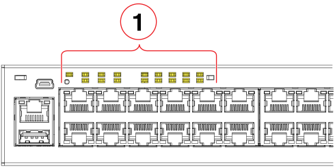
The following figure shows an example of the system status LEDs.
Note: Not all models have all the LEDs and the location of the LEDs on the front panel may
also be slightly different.
System status LEDs on the
ICX 7250-48P
System status LEDs
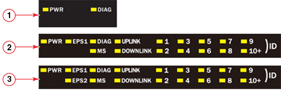
The following figure shows the system status LEDs for
ICX 7250 models.
System status LEDs for
ICX 7250 models
ICX 7250-24G LEDs
ICX 7250-24,
ICX 7250-24P,
ICX 7250-48 LEDs
ICX 7250-48P LEDs
System status LEDs
LED
Condition
Status
PWR
Green
Power supply is operating normally.
Yellow
Power supply fault.
Off
Power supply off.
EPS1 and EPS2 (for supported models)
Green
EPS1 and EPS2 power supplies are operating normally.
Yellow
EPS1 and EPS2 power supply fault.
Off
EPS1 and EPS2 off or not present.
DIAG
Flashing Green
System self-diagnostic test in progress. System reloads automatically.
Steady Yellow
System self-diagnostic test has detected a fault. (Fan, thermal, or any interface
fault.) The user must reload the system.
MS
Green
The device is the Active controller. Flashing indicates the system is initializing.
Yellow
Indicates the device is the Standby controller. Flashing indicates the system is
in Master arbitration or selection state.
Off
Device is operating as a stack member, or is in standalone mode.
UPLINK
Green
Uplink port is operating normally.
Off
Uplink has failed or there is no link.
DOWNLINK
Green
Downlink port is operating normally.
Off
Downlink has failed or there is no link.
1-10+ (ID)
(Switch ID in the stack)
Green
Indicates the switch ID in the stack.
The switch can display up to 19 switch IDs. The 10+ LED is used in conjunction with
the 1 through 9 LEDs to indicate numbers greater than 10. The number of devices supported
in a stack is 12.