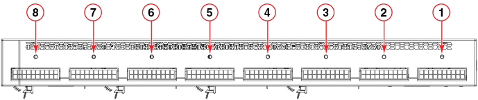
EPS4000 front and rear panels
There are 32 LEDs on the front panel of the EPS4000 to indicate the status for the DC power on the 8 ports. 16 LEDs (Ex.y) are for the 54 VDC and the other sixteen (Rx.y) are for the 12 VDC supply. There is a reset button next to the LEDs. There are port LEDs for each of the management ports. Both the serial port and the out-of-band Ethernet management ports use RJ-45 connectors. The slots for the RPS17 PSUs are covered with slot covers. The slot cover must be removed to install the PSU.
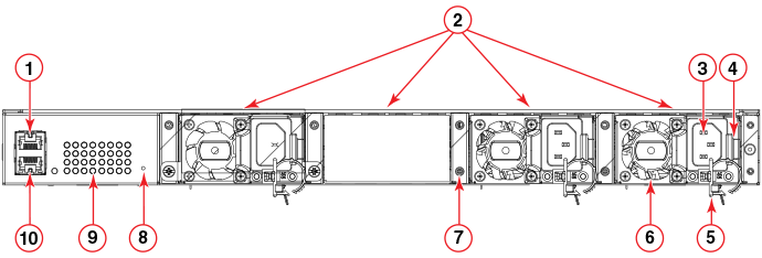
- Management console serial port (RJ-45)
- RPS17 PSU slots (three populated, one with cover on)
- AC power cord input (C14)
- PSU release latch
- Power cord clip
- Integrated RPS17 PSU fan
- PSU slot cover screws
- Reset button (sets EPS4000 configuration to factory default)
- System status indicators
- Out-of-band, Ethernet management port (RJ-45)