Connecting the EPS4000 cord
There are two types of EPS4000 cords available, 1:1 and 1:2. The 1:1 cord can deliver 740 W at 54 V to one switch. The 1:2 cord can deliver 370 W at 54 V to each of two switches from one port on the EPS4000 power supply. Both cords deliver up to 120 W at 12 V. You must use a 1:2 cord if you want an ICX 7250-48P device to share 54-V power with another device. Both 1:1 and 1:2 cords will deliver only 370 W of 54 V power to an ICX 7250-24P device.
The following figure shows EPS4000 DC power cords
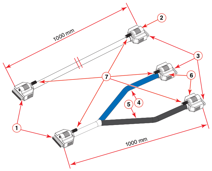
- Connector headers EPS4000 side (black)
- Switch side connector housing (1:1 cord)
- Connector headers switch side (white)
- Port #2 cord (Blue)
- Port #1 cord (Black)
- Switch side connector housing (1:2 cord)
- Latch screws
Complete the following steps to connect the EPS4000 cord.
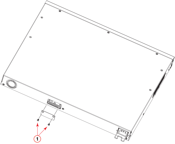
- Using a Phillips screwdriver, remove the two screws on the EPS4000 faceplate of the external power receptacle.
- Attach the port side connector of the EPS4000 DC cord to the switch.
- Attach the EPS4000 side connector of the EPS4000 DC cord to an available DC power port on the back of the EPS4000.
- Use a flat-blade screwdriver to attach the latch screw on the DC cord to the
EPS4000.
When the screw is tightened securely, all power supplies to your device will be active.