Configuring a VLAN
Complete the following steps to configure a VLAN.
- Select . You can perform the following actions:
- Clone a VLAN: To learn more about VLAN cloning, refer to Cloning a VLAN.
- Add a VLAN: Continue to step 2 to configure a new VLAN.
- Search and view existing VLANs: To view existing VLANs, follow one of the following methods:
- Edit a VLAN: Select an
existing VLAN from the list. Select the required ports to add or remove the
ports from the VLAN. Make the necessary changes and select Apply.
Note: If you want to use the VLAN ID "VLAN 1" as a configurable VLAN, you can assign a different VLAN ID to the default VLAN. You must specify a valid VLAN ID that is not already in use. Reassigning a different VLAN ID to the default VLAN does not change the properties of the default VLAN, but allows you to use the VLAN ID "VLAN 1" as a configurable VLAN.Note: The VLAN name is not editable after a VLAN is configured.
- Delete a VLAN: Select a
configured VLAN from the list and select
 . The Delete VLAN confirmation dialog box displays.
Select Apply to delete the selected VLAN.
. The Delete VLAN confirmation dialog box displays.
Select Apply to delete the selected VLAN.
- Select
 to create a new VLAN.
 - Complete the following
fields:
- VLAN Id: Enter an ID
for the VLAN.
You can configure up to 4094 port-based VLANs on a Layer 2 switch or Layer 3 switch. On both device types, valid VLAN IDs are 1 through 4095. You can configure up to the maximum number of VLANs within that ID range. By default, all the ports on a RUCKUS device are in a single port-based VLAN. This VLAN is called the DEFAULT-VLAN and is VLAN 1.
- VLAN Name: Enter a name for the VLAN. The name can be up to 32 characters in length.
- VLAN Id: Enter an ID
for the VLAN.
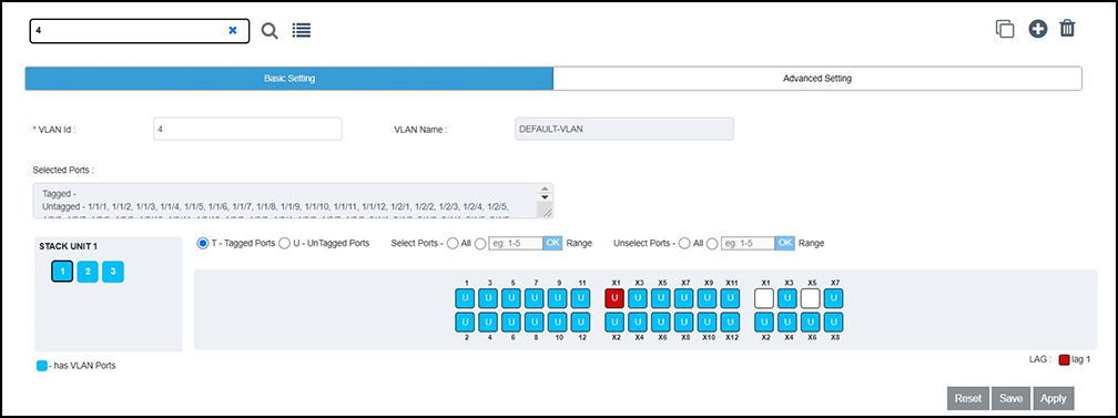
- In the Basic
Setting tab, add ports to the VLAN by performing the following
actions:
- Select a unit ID box in the STACK UNIT panel to view the corresponding port panel of the stack unit.
- To add tagged ports, select T-Tagged Ports and select the required ports on the ports panel. To remove the added ports, select the ports again on the ports panel.
- To add untagged ports,
select U-UnTagged Ports and select the required ports on the
ports panel. To remove the added ports, select the ports again on the
ports panel. The color code of the stack unit indicates that the ports of that unit are associated with the VLAN. The color of the ports in the ports panel indicates that the ports are part of the VLAN. The letter T represents a tagged port and the letter U represents an untagged port.
- Choose the following options common to tagged ports and untagged ports:
- In the Advanced
Setting tab, configure the required features at the VLAN
level:
- IGMP
Snooping: Configures IGMP snooping for a VLAN, and sets
the IGMP mode as active or passive.
- Active: Configures IGMP active mode so that the device actively sends out IGMP queries to identify multicast groups on the network, and makes entries in the IGMP table based on the group membership reports it receives.
- Passive: Configures IGMP passive mode so that the device does not send queries but forwards reports to the router ports that receive queries. When passive mode is configured on a VLAN, queries are forwarded to the entire VLAN.
- Multicast Version: Configures the IGMP version for snooping on a VLAN.
- Spanning Tree: Enables the STP version on a VLAN.
- Spanning Priority: Configures the priority of the bridge in a spanning tree (instance of STP). The bridge with the lowest value has the highest priority and is the root. A higher numerical value means a lower priority; thus, the highest priority is 0.
- ARP Inspection: Enables or disables ARP inspection.
- IP4 DHCP Snooping: Enables or disables IP4 DHCP snooping.
- IGMP
Snooping: Configures IGMP snooping for a VLAN, and sets
the IGMP mode as active or passive.
- Select Apply. The Port Setting dialog box displays,which shows the tagged and untagged ports that are selected and removed as part of the VLAN configuration.
- Select OK to apply the VLAN configuration to the device.
 to the configured VLANs are displayed
in a list. Select a VLAN to view the configuration details.
to the configured VLANs are displayed
in a list. Select a VLAN to view the configuration details. to view the configuration details.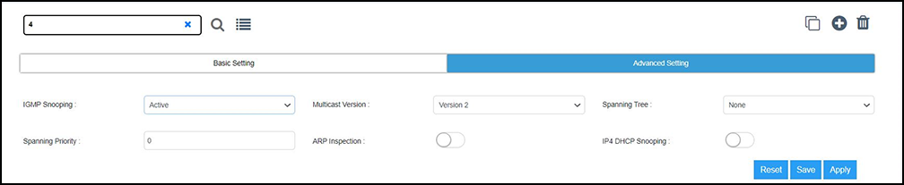
Cloning a VLAN
An existing VLAN can be cloned to create a new VLAN with all the configurations of
the
originally configured VLAN.
 . The
. The