Installing a New Fiber-Optic Transceiver
Support will not be provided if there is an issue with a third-party transceiver.
You can install a new transceiver in a slot while the device is powered on and running. For ports not configured in breakout mode, a fixed speed can also be set using the CLI (refer to the RUCKUS FastIron Management Configuration Guide). Port speed changes are dynamic and do not require a system reboot.
Installed transceivers are validated against a predefined list and categorized as Qualified, Unqualified, or Unsupported. Qualified transceivers operate normally. Unqualified transceivers are allowed to operate, but a log message is generated to inform the user. Unsupported transceivers are rejected and a port fault log message is generated.
Before installing a fiber-optic transceiver, wear a properly grounded ESD wrist strap.
Use the following steps to install a transceiver:
- Put on the ESD wrist strap and ground yourself by attaching the clip end to a metal surface (such as an equipment rack) to act as ground.
- Remove the new transceiver from the protective packaging.
- Remove any protector plugs from the transceivers and the ports.
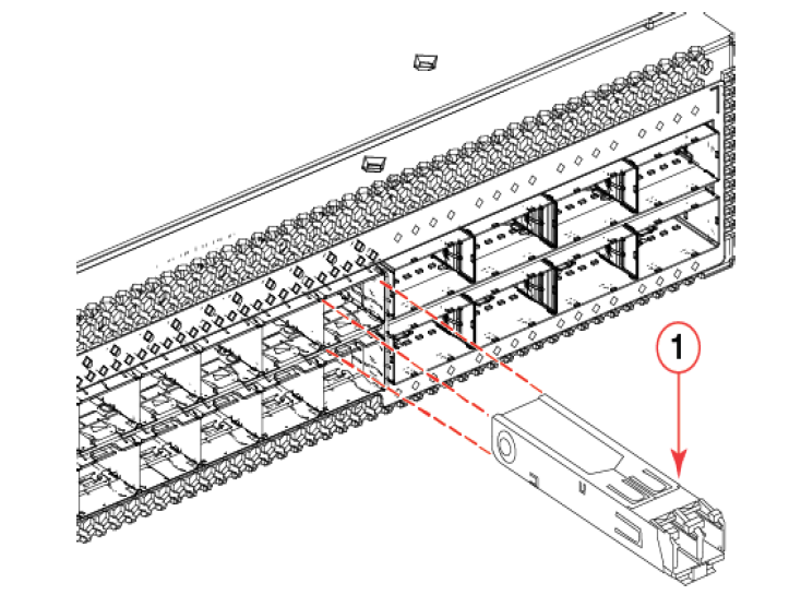
- Making sure that the bail (wire handle) is in the unlocked position, place the transceiver in the correctly oriented position on the port, as shown in the following figure.
- Slide the transceiver into the port until you feel it click into place; then close
the bail. Transceivers are keyed to prevent incorrect insertion.
Note: Each fiber-optic transceiver has a 10-pad gold-plated edge connector on the bottom. The correct position to insert a fiber-optic transceiver in the upper row of ports is with the gold-plated edge down. The correct position to insert a fiber-optic transceiver in the lower row of ports is with the gold-plated edge up.