Deployment Procedure
The following are basic instructions for setting up vSZ-D on LINUX KVM.
- Download the Data Plane package (.qcow2 file) from Ruckus support .
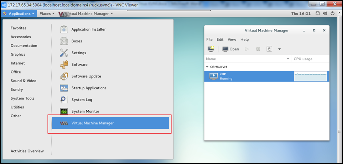
- From the VNC Viewer, click System Tools > Virtual Machine Manager to open the Virtual Machine Manager tool. The Data Plane status must appear Running as shown in the following figure.
- Create a new VM.
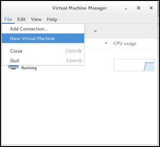
- Click File and select New Virtual Machine as shown in the following figure.
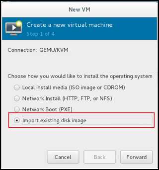
- In the New VM dialog box, choose the disk format option as shown in the following figure.
- Click Forward.
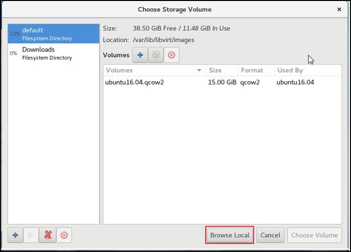
- Choose destination storage path and storage volume. Click Browse Local as show in the following figure.
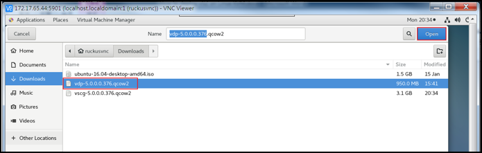
- Select the Data Plane file and click Open as shown in the following figure.
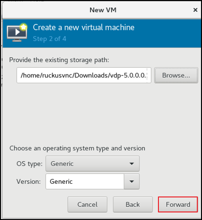
- To select the storage path, click Browse as shown in the following figure.
- Click Forward.
-
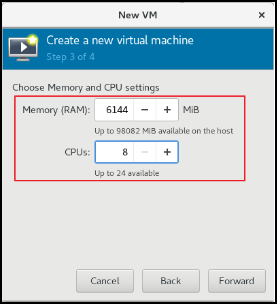
5.0 UpdateEnter the Memory (RAM) and CPUs setting as shown in the following figure.
- Click Forward.
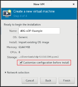
- To confirm the installation process, click Finish as shown in the following figure.
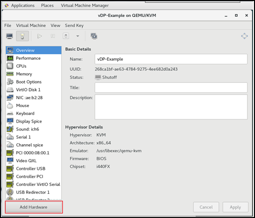
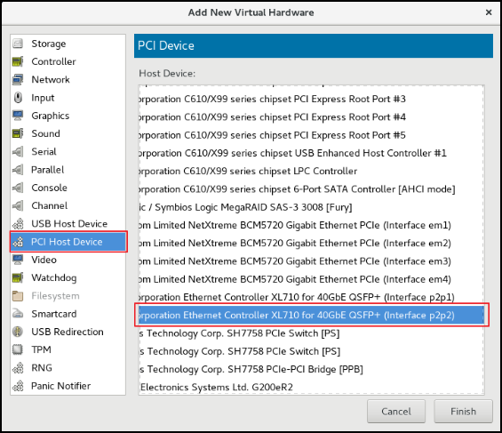
- 4. Add another NIC as Data Plane needs two interfaces; Management and Data. From the VNC Viewer and click Add Hardware > PCI Host Device > PCI Device to add another NIC as shown in the following figure.
- Select PCI Host Device > PCI Device and click Finish to add another NIC as shown in the following figure.
-
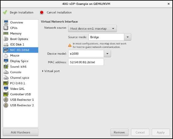
How do we get to this page?Select the NIC and choose the Device model to update the management interface associate as shown in the following figure.
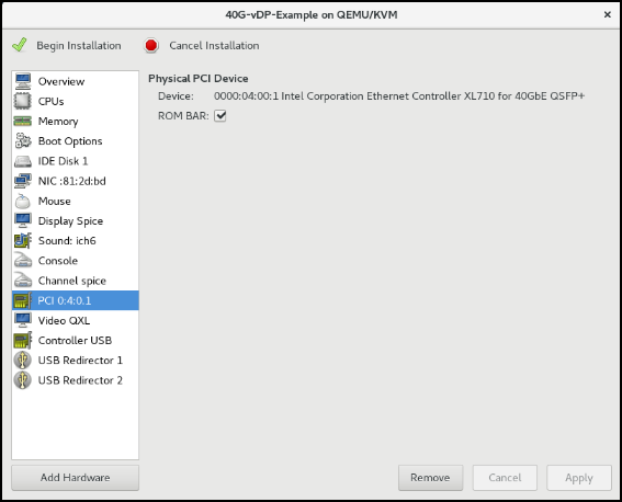
- From PCI, select the ROM BAR check box to define the Data IP domain as shown in the following figure.
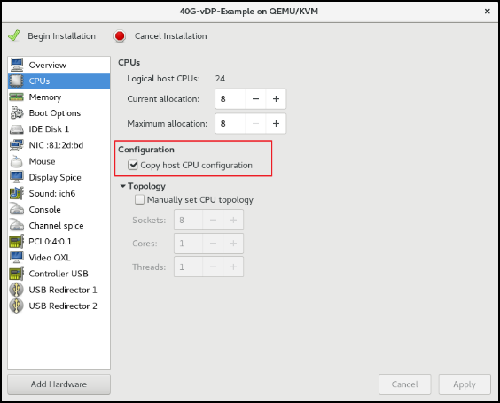
- Define the CPU Configuration. Select the Copy host CPU configuration check box as shown in the following figure.
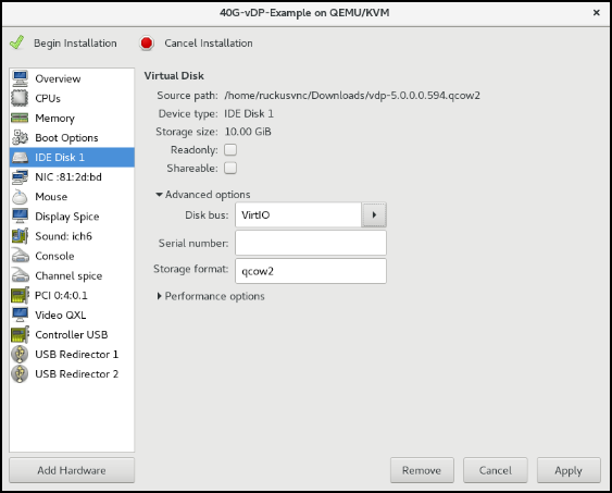
- Define the IDE Disk Configuration. Choose the Disk bus option as shown in the following figure.
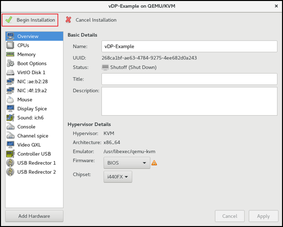
- Select Begin Installation as shown in the following figure.
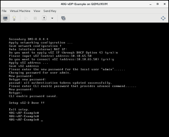
- The Data Plane setup is complete as shown in the following image.