BPDU Tunneling over Selective Q-in-Q
BPDU tunneling over selective Q-in-Q enables a service provider to provide Layer 2 VPN connectivity between different customer sites. The service provider can give the customers an infrastructure to run various Layer 2 protocols and connect to all geographically-separated sites.
In Q-in-Q BPDU tunneling, a customer packet transferred through the service provider network is tagged twice (except for untagged customer traffic which has only one outer tag). Apart from the customer’s IEEE 802.1Q VLAN tags (CVLAN), a service VLAN tag (SVLAN) is also added on all the frames. By adding different VLAN tags for each customer, traffic (control/protocol/bpdu for which tunneling is enabled) from different customers can be segregated and transferred throughout the service provider network without any VLAN conflict. Also, the service provider network is transparent to the customer and can run STP (PVST, RSTP, MSTP), LACP, CDP, and LLDP seamlessly using the Layer 2 tunneling.
How Q-in-Q BPDU Tunneling Works
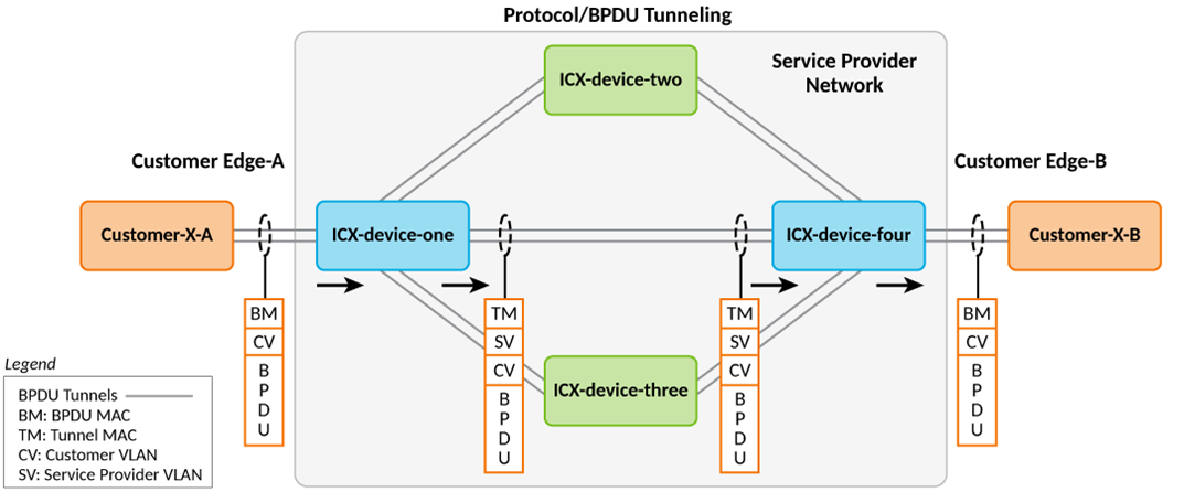
When Q-in-Q BPDU tunneling is enabled, the service provider (ingress) edge device receives the BPDU packets and delivers the packets to the CPU along with CVLAN and SVLAN information. Upon ingress to the service provider network, the protocol or BPDU MAC address is replaced with a tunnel MAC address and is sent across the service provider network. Intermediate devices on the service provider network forward the frame as an unknown multicast packet. Upon egress from the service provider network to the customer network, the tunnel MAC packets are decapsulated and delivered to the customer edge device. For Layer 2 protocols such as LACP and STP to converge properly, point-to-point connections must be emulated for each port using a unique customer-to-service VLAN.
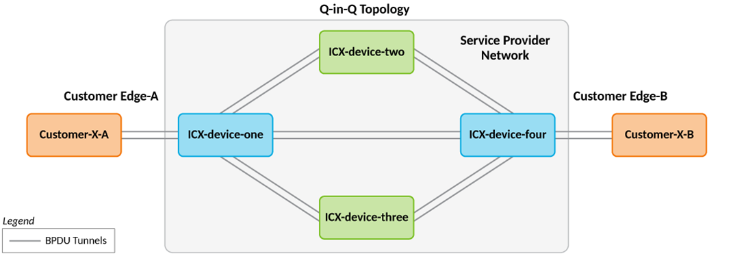
In the following topology, Customer X site A and Customer X site B are connected in the service provider network through Q-in-Q BPDU tunneling. Both data and control packets coming from the customer site with customer VLAN (CVLAN) are double-tagged with a Service VLAN (SVLAN).
The Protocol or BPDU packet format at various stages is shown in the following topology.
Q-in-Q BPDU tunneling does not affect any Class of Service (CoS) values that are configured on the CVLAN. Ingress priority and CoS settings from the CVLAN are copied to the SVLAN. CoS values do not change in the reverse direction (SVLAN to CVLAN).
Scaling Considerations for BPDU-Tunneling over Selective Q-in-Q
BPDU-tunneling is used to tunnel layer2 BPDUs between customer sites over the service provider network. All the incoming BDPUs are forwarded in the slow path or CPU. Even though the total number of tunneled CVLANs is increased to 8000 per stack unit, the number of BPDUs that can be tunneled is limited, resulting in CPU load.
BPDU tunneling is now supported over selective Q-in-Q. But BPDU tunneling cannot be achieved without Q-in-Q tunnel. Disabling selective Q-in-Q tunnel removes the BPDU tunneling configurations from the interface.
If Bridge Protocol Data Unit (BPDU) tunneling feature is configured on the selective Q-in-Q enabled port, then BPDU tunneling is applicable only for the mapped CVLANs. BPDUs received on the unmapped CVLANs is processed in the regular manner.