BGP EVPN Configuration
A VXLAN network is composed of two
primary components: the underlay and the overlay networks. Virtual Tunnel Endpoints
(VTEPs)
are positioned at the boundaries of the underlay network, enabling Layer 2 and Layer
3
connectivity between customer edge devices, or tenant systems, within the overlay
network.
The underlay network serves as a logical switching fabric, supporting the tenant
systems in
the overlay network.
Configuring BGP EVPN involves four main steps:
- Configuring the Underlay Network
- Configuring iBGP EVPN Peering Between VTEPs
- Configuring EVPN Instances for the Overlay Network (this step is not required for Route Reflectors (RR).
- Configuring the Overlay for VXLAN Routing
-
Come back to this listConfiguring the Underlay Network
- Configuring the Overlay Gateway
- Configuring iBGP EVPN Peering Between VTEPs
- Configuring EVPN Instances and VNIs .
Come back to this
Refer to these sections
for more information:• Configuring BGP EVPN in a Route Reflector Scheme on page XX
• Configuring BGP EVPN in a Full Mesh Scheme on page XX
Typical BGP EVPN Single-homed Network Topology
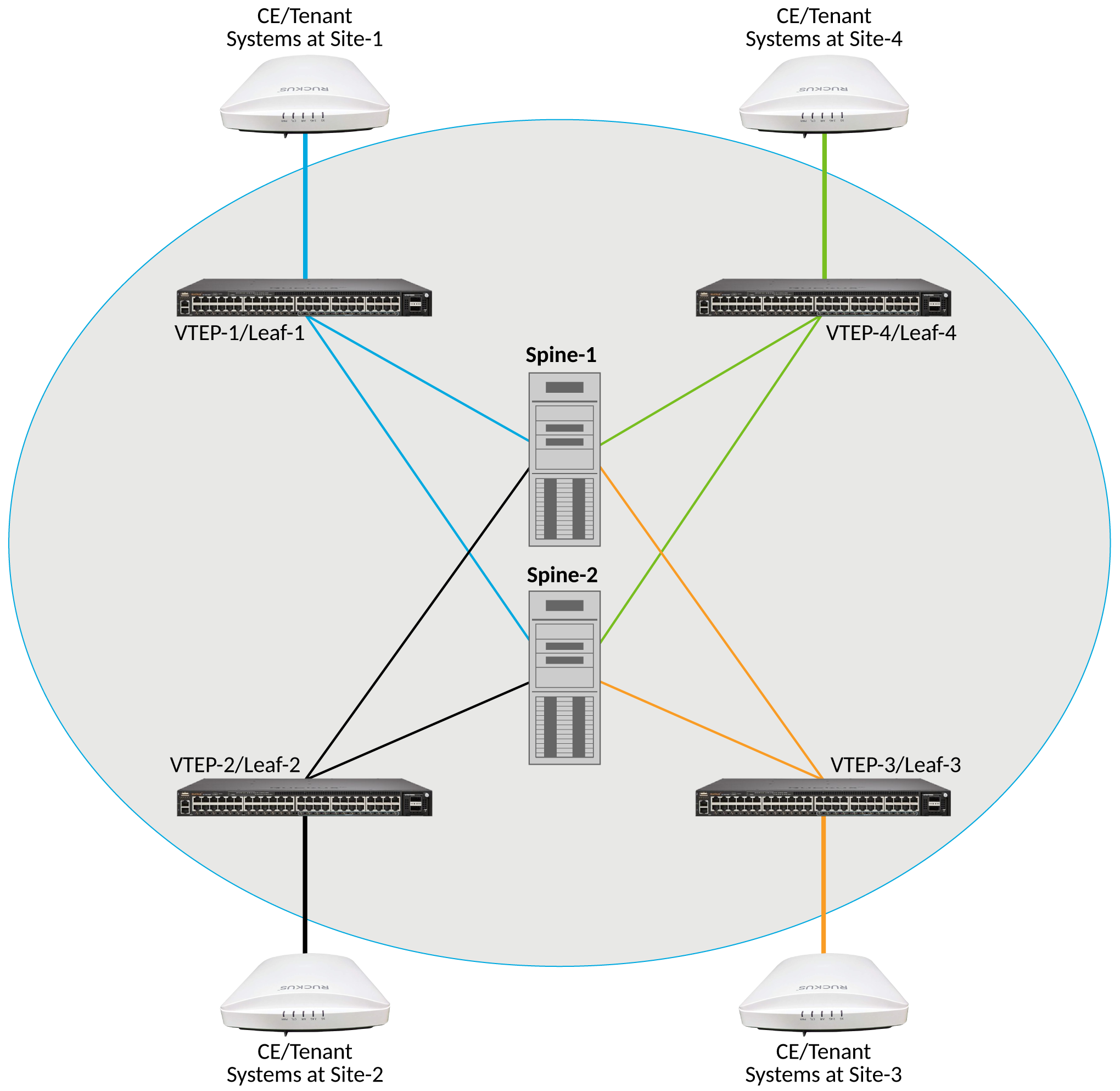
The illustration below shows a typical BGP EVPN network topology. Here, a leaf-spine topology comprises VTEPs (also known as "leaf" devices) and "spine" devices. The spine devices connect all the leaf devices within the underlay network, thereby supporting BGP peering. This image shows a single-homed BGP EVPN topology that consists of four customer sites.
This topology includes the following components and considerations:
- Each customer site has one Virtual Tunnel Endpoint (VTEP).
- Every VTEP is connected to the spine devices in the underlay network.
- VTEP-to-VTEP communication occurs through the spine devices.
- The underlay network can run OSPF or RIP between the VTEPs and spine devices to establish Layer 3 connectivity.
- iBGP EVPN peers are part of the underlay network.
- Internal BGP (iBGP) is used to propagate routes within a single Autonomous System (AS).
- Loopback addresses configured on the VTEPs are used for both iBGP EVPN peering and VXLAN tunnel endpoints.