Wake-on-LAN support across VLANs
The WOL technology makes use of specially formatted network packets (often referred to as a "magic" packet generated through a software utility) that contains the target PC's MAC address to wake up the remote clients. The magic packet is mostly based on UDP and is sent to clients that are enabled to respond to these packets. The WOL technology allows administrators to remotely power on the PC and perform scheduled maintenance tasks even if the user has powered the system down. By remotely triggering the computer to wake up, the administrator does not have to be physically present to perform maintenance tasks on each computer on the network.
The WOL technology works based on the principle that when the PC shuts down, the Network Interface Card (NIC) continues to receive power, and keeps listening on the network for the magic packet to arrive. The magic packet is based on User Datagram Protocol (UDP). The client PCs on different subnets/VLANs can be turned on remotely by a WOL server. The following transmission methods are used to send the magic packet from source to destination machine.
The magic packets are transmitted directly to the target machine IP address. This method uses targeted host IP address (example 192.168.1.10/24) as a destination address. The magic packet is unicast-forwarded through all router hops until it reaches the destination subnet. At each router hop, the destination Media Access Control (MAC) address of the forwarded packet is the next-hop router's local interface MAC address for unicast forwarding to the next-hop router, or the target host's MAC address for unicast forwarding within the destination subnet. The destination IP address will not change.
The magic packets are transmitted to the target machine subnet IP address. This method uses the broadcast address of the destination subnet IP address (example 192.168.1.255/24) as a destination address that stands for all machines in the local subnet, and it uses the MAC address of the target machine from the database to generate a wake-up packet. The magic packet is unicast-forwarded through all router hops until it reaches the destination subnet. At each router hop, the destination MAC address of the forwarded packet is the next-hop router's local interface MAC address for unicast forwarding to the next-hop router, or FF-FF-FF-FF-FF-FF for directed broadcast forwarding to all nodes within the destination subnet. The destination IP address will not change.
The magic packets are transmitted to the broadcast IP address of a subnet to which the sending machine is not directly attached. This method uses the broadcast address 255.255.255.255 as a destination address. The magic packet is transmitted in layer 3 and layer 2 based on the following router distance between the source and destination networks:
- Layer 3
- If there is only one router between the source and destination networks, a copy of the packet is broadcast-forwarded to the destination subnet(s) specified in the IP Helper(s) of the router's inbound interface at the router hop. If no forwarding is defined for the WOL UDP port, the packet is dropped.
- If there are multiple routers between the
source and destination networks, a copy of the packet is
unicast-forwarded to the destination subnet(s) specified in the IP
Helper(s) of the router's inbound interface at the first router hop. If
no forwarding is defined for the WOL UDP port, the packet is
dropped.
Note: You must enable directed broadcast functionality on the last-hop router's outbound-to-users interface(s). If the packet is to be forwarded to all users everywhere, then all routers with connected users are effectively acting as last-hop routers.
- At the intermediate router hops, the packet continues to be unicast-forwarded, at the final router hop, upon being allowed the directed broadcast is forwarded onto the destination subnet. If Directed Broadcast is not enabled, then the packet is dropped.
- Layer 2
- At each router hop, the destination MAC address of the forwarded packet is FF-FF-FF-FF-FF-FF for broadcast forwarding to all nodes within the destination subnet, or the next-hop router's local interface MAC address for unicast forwarding to the next-hop router, or FF-FF-FF-FF-FF-FF for directed broadcast forwarding to all nodes within the destination subnet.
ICX devices natively support or switch the magic packets. However, by default, ICX
devices do not forward requests for UDP applications to different subnets or VLANs.
So, the ICX device must be configured to forward the directed broadcasts for the magic
packet to be sent over the sleepy ports using the
ip forward-protocol udp command.
You must also configure a helper address on the
VLAN of the WOL server to join the subnet of the desired clients using the ip helper-address command.
You must specify the broadcast address of each client network as this is the only
way to
send a packet to a PC that is shut down. Because the PC is asleep, the PC will
not
respond to ARP requests as it does not own its IP when the PC is down. The forward
protocols would be set up to include UDP port (7) echo to trigger the wake-up of
the
remote machine.
Prerequisites
The following checks must be done before deploying WOL across several subnets to wake up the target client PC:
- Check the BIOS settings and ensure that Wake-On-LAN is enabled.
- Check the NIC Advanced Settings and ensure that Magic & Directed Packets are accepted.
- Connect the WOL server and the desktop or laptop client to the same VLAN.
- Invoke Wake Up PC from Software utility
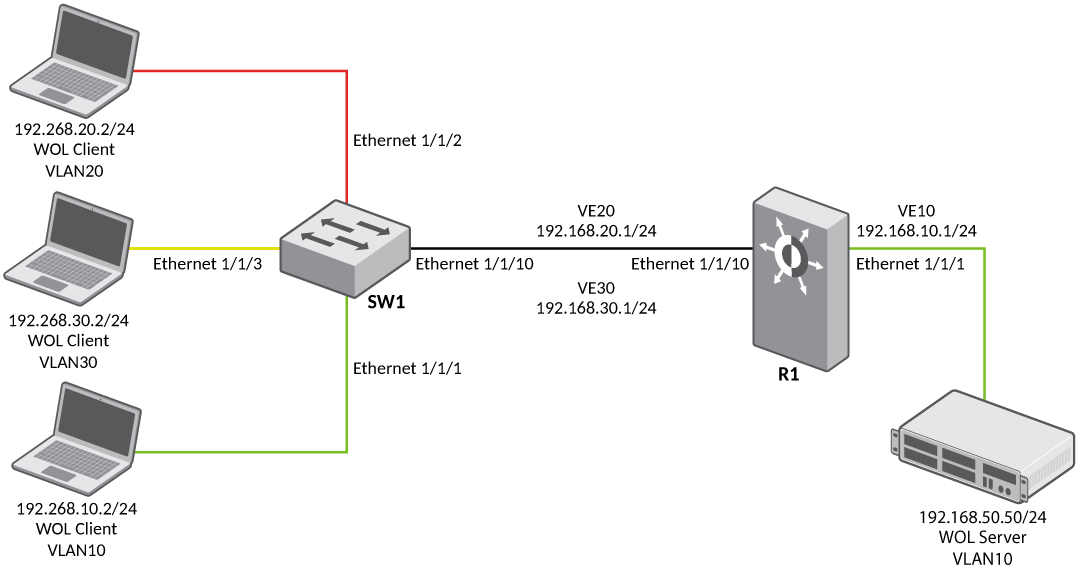
Following is a sample configuration for Wake-On-LAN (WOL) support across different VLANs:
- Router R1 (inter-VLAN)
configuration:
device(config)# vlan 10 name server_vlan  by port
device(config-vlan-10)# tagged ethernet 1/1/10
device(config-vlan-10)# untagged ethernet 1/1/1
device(config-vlan-10)# interface ve 10
device(config-vlan-10)# exit
device(config)# vlan 20 name user_vlan  by port
device(config-vlan-20)# tagged ethernet 1/1/10
device(config-vlan-20)# interface ve 20
device(config-vlan-20)# exit
device(config)# vlan 30 name user_vlan  by port
device(config-vlan-30)# tagged ethernet 1/1/10
device(config-vlan-30)# interface ve 30
device(config-vlan-30)# exit
device(config)# ip forward-protocol udp echo
device(config)# interface ve 10
device(config-vif-10)# ip address 192.168.10.1 255.255.255.0
device(config-vif-10)# ip helper-address 1 192.168.20.255
device(config-vif-10)# ip helper-address 2 192.168.30.255
device(config-vif-10)# interface ve 20
device(config-vif-20)# ip address 192.168.20.1 255.255.255.0
device(config-vif-20)# interface ve 30
device(config-vif-30)# ip address 192.168.30.1 255.255.255.0
- Switch (SW1)
configuration:
device(config)# vlan 10 name server_vlan  by port
device(config-vlan-10)# tagged ethernet 1/1/10
device(config-vlan-10)# untagged ethernet 1/1/1
device(config-vlan-10)#  exit
device(config)# vlan 20 name user_vlan20 by port
device(config-vlan-20)# tagged ethe 1/1/10
device(config-vlan-20)# untagged ethe 1/1/2
device(config-vlan-20)# exit
device(config)# vlan 30 name user_vlan30 by port
device(config-vlan-30)# tagged ethernet 1/1/10
device(config-vlan-30)# untagged ethernet 1/1/3