Transparent Clock
The following figure shows a typical clock distribution topology in the network.
Typical Clock Distribution Topology
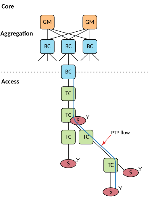
GM - Grandmaster clock-regional
BC - Boundary Clock
TC - Transparent Clock
S - Slave Clock
Y - End Device
The following figure shows a clock topology with redundant clock sources in the network.
Topology with Redundant Clock Sources
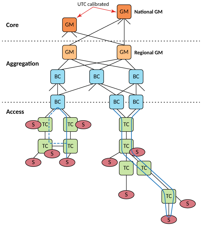
GM - Grandmaster clock-regional
BC - Boundary Clock
TC - Transparent Clock
S - Slave Clock
End-To-End Delay Mechanism
The following figure shows an ideal End-to-End delay mechanism.
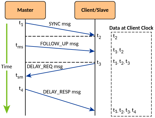
One-step PTP Transparent clock with One-step Master
- The master clock sends a SYNC message to the slave device. As the SYNC message leaves the physical interface of the master clock, it captures a timestamp (t1).
- The slave clock receives the SYNC message and the clock captures the time (t2) when the SYNC message arrives at its physical port. Due to the propagation delay in the wire, there will be a slight time difference between the slave timestamp clock and the master clock.
- A delay request message is then sent to the master clock to the slave clock to calculate the time difference between them. The slave clock running timestamp captures the time (t3) as soon as the message starts transmitting out the physical interface of the slave.
- The master clock receives the delay request and uses the master clock running timestamp to capture the time (t4) when the message starts receiving on its physical interface.
- The master clock sends the slave clock a delay response message containing the captured t4 value. The slave clock receives the delay response message with the t4 value and adjusts itself to synchronize with the master clock.
One-step End-to-End Transparent Clock with Two-Step Master
- The master sends out a SYNC signal with the two-stepFlag set to TRUE, but without a precise departure timestamp.
- Hardware receive (Rx) time stamping occurs when the SYNC message is received.
- SYNC messages are forwarded to the egress along with the Rx timestamp. Ingress Stage 2 (IS2) is configured to perform one-step PTP time stamping.
- Hardware transmission (Tx) time stamping occurs at the egress point. Residence time is calculated by subtracting the Rx timestamp from the current delay timer. Residence time is added to the correction field of the SYNC message.
- Send the SYNC frame with the updated Frame Check Sequence (FCS). The Slave clock redirects the sync signal to the CPU to receive t2.
- Master sends a FOLLOW_UP message and forwards it to egress without the Ingress Stage 2 action.
- The slave clock redirects the FOLLOW_UP message to the CPU and calculates t1 using information from both the SYNC and FOLLOW_UP messages.
- A delay request message is sent from the master clock to the slave clock to calculate the time difference between them. As soon as the message begins transmitting through the physical interface of the slave clock, the slave clock records the timestamp (t3).
- The master clock receives the delay request and captures the time (t4) when the message starts being received on its physical interface.
- The master clock sends a delay response message to the slave clock, which contains the captured t4 value. Upon receiving the delay response message with the t4 value, the slave clock adjusts itself to synchronize with the master clock.
IEEE Standard 1588-2008 Message Format
The following table shows the common message format according to IEEE Standard 1588-2008.
The End-to-End Transparent Clock Overcomes Clock Errors
When the PTP event message flows continuously through a network, it experiences packet delay and latency. The PTP-TC-enabled devices can overcome this delay by adjusting the correctionField in the PTP message to compensate for the residence time within the network. The PTP-TC is implemented as part of the Packet Processor. The ICX software enables the timestamping capability on a given port based on the user input or configuration. The implementation of the end-to-end transparent clock requires the residence time of the device, which is the time it takes the event message to transmit from ingress port to egress port. The calculated residence time is added to the correctionField of the event message. The end-to-end transparent clock uses the SYNC, DELAY_REQ, and DELAY_RESP event messages.
Residence time: A transparent clock generates an ingress timestamp when a PTP event message reaches the ingress port, and generates an egress timestamp when the PTP event message leaves the egress port. The residence time for each PTP event message can be computed for each egress port. The residence time is equal to the egress timestamp minus the ingress timestamp.
One-step transparent clocks: The residence time can be added to the correctionField of the SYNC event message by the egress port during the transmission of the SYNC message. The egress port can make any required corrections to the fields in the SYNC message.
End-to-End Transparent Clock Recovery Mechanism
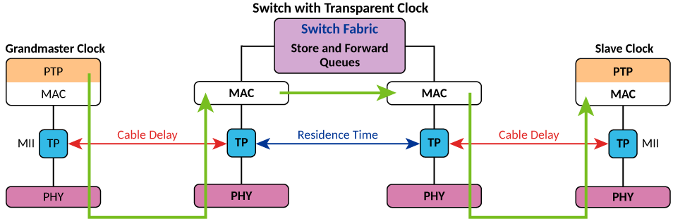
PTP - Precision Time Protocol
MAC - Media Access Control
MII - Media-Independent Interface
TP - Timestamp Point
PHY - Physical Layer
The following topology shows the use case of PTP-TC using the ICX devices supporting PTP.
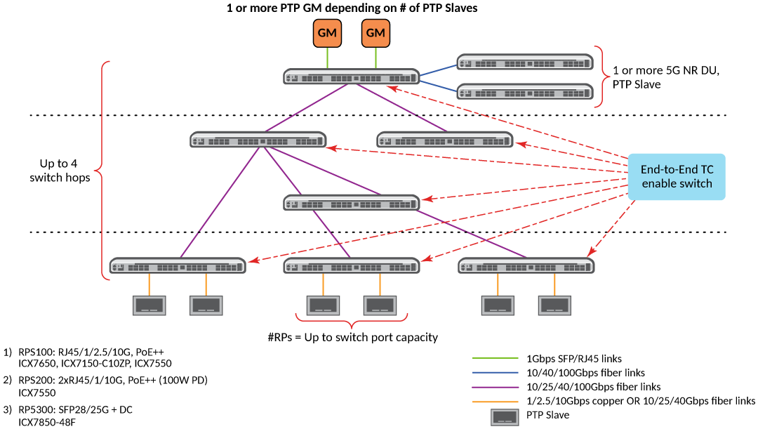
Beginning with FastIron release 08.0.95, updates are allowed to the correctionField on PTP event messages for the following types of PTP packets:
- Ethernet frame with EtherType of 0x88F7.
- Support PTP messages with MAC addresses as specified in the following table.
FastIron 08.0.95 supports timestamping of PTP messages on ingress and egress ports, provided PTP-TC is enabled on the participating ports.
Beginning with FastIron release 08.0.95, end-to-end PTP-TC mode of operation is supported for standalone and stacking topologies. The software treats the stacking as a chain of PTP-TC devices connected back-to-back, and each device updates the correctionField to eliminate the residence time within the switch.
Beginning with FastIron release 08.0.95, the highest priority is automatically assigned to the PTP messages that are untagged or are not part of the IEEE Standard 802.1Q encapsulated frames. The messages encapsulated as part of the IEEE Standard 802.1Q frame follow the IEEE Standard 802.1P priority carried in the Ethernet frame.