VXLAN Gateway Overview
VXLAN is mostly compliant with RFC 7348: Virtual eXtensible Local Area Network (VXLAN): A Framework for Overlaying Virtualized Layer 2 Networks over Layer 3 Networks. The main difference is how Broadcast, Unknown Unicast, and Multicast (BUM) traffic in the overlay is handled. While RFC 7348 recommends using multicast in the Layer 3 underlay, the FastIron VXLAN implementation uses static-ingress replication to forward overlay (Layer 2) BUM traffic.
VXLAN provides an overlay for Layer 2 and Layer 3 data center networks that support multi-tenant environments. It creates a logical Layer 2 network over an existing Layer 3 infrastructure to meet cloud-scale requirements.
VXLAN extends the VLAN address space with a 24-bit segment ID called a VXLAN Network Identifier (VNI), enabling up to 16 million VXLAN segments. The VNI in each frame isolates individual logical networks, allowing millions of Layer 2 VXLAN segments to coexist on a common Layer 3 network. Each VLAN is mapped to a unique VNI to extend the Layer 2 VLAN segment to remote locations.
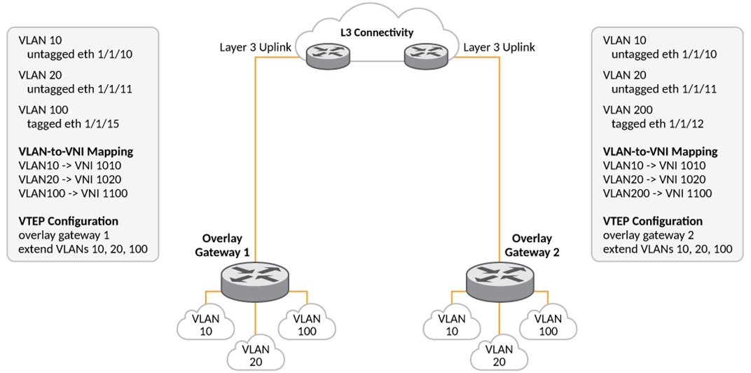
The following figure shows VXLAN gateways providing Layer 2 connectivity between two switches across a Layer 3 network, so users connected to the same VLANs on both switches operate as if they are on the same Layer 2 network.
VXLAN Ethernet Frame Encapsulation
VXLAN tunnels Layer 2 overlay traffic across a Layer 3 network. Communication occurs between two tunnel endpoints called Virtual Tunnel End Points (VTEPs). VXLAN uses MAC Address-in-User Datagram Protocol (MAC-in-UDP) encapsulation: it wraps Layer 2 MAC frames in a Layer 3 UDP packet, adding an outer Ethernet header, outer IP header, outer UDP header, and a VXLAN header. The outer IP header carries the source and destination VTEP IP addresses.
VTEPs perform encapsulation and decapsulation, mapping tenant traffic to and from the virtual network. A tenant’s Layer 2 frame is wrapped in a Layer 3 UDP packet and sent to the remote VTEP. The remote VTEP removes the outer headers and forwards the original Layer 2 frame to the tenant network.
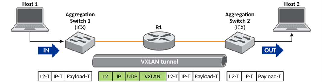
Because VXLAN is a tunneling technique, a VXLAN gateway is required to carry traffic between VXLAN and traditional VLANs. In aggregation-switch deployments, VXLAN gateway mode establishes a Layer 2 tunnel between two VXLAN gateways, extending the VLAN across a Layer 3 underlay. The FastIron VXLAN gateway enables communication between VXLAN-aware and non-VXLAN-aware domains and provides E-LAN (multipoint-to-multipoint) service using full-mesh connectivity between VTEPs.
The FastIron implementation of VXLAN supports the following features:
- Multiple VNIs over the same VXLAN tunnel: RUCKUS supports multiplexing and demultiplexing multiple VNIs over the same VXLAN tunnel to improve deployment scalability.
- Multiple VXLAN tunnels: RUCKUS supports multiple VXLAN tunnels on a VTEP. These tunnels can
use the same or different uplink ports. For multiple Layer 2 tunnels, the
following constraint applies:
If two or more Layer 2 tunnels share the same outgoing interface (Layer 2 port), their outer Layer 2 headers (Destination MAC, Source MAC, and VLAN header) must be identical. In other words, the Layer 3 outgoing interface, VRF, and the next-hop address must be the same for the two tunnels.
- VLAN translation across VXLAN segment: Because the VLAN tag is removed from the Layer 2 payload frame before VXLAN encapsulation, VXLAN can interconnect the same Layer 2 subnet even when different VLAN identifiers are used on each VTEP. For example, as shown in VXLAN Gateway, VLAN 100 on the Overlay Gateway 1 and VLAN 200 on the Overlay Gateway 2 are interconnected by mapping those VLANs to the same VNI (1100).
- Interoperation with other VXLAN implementations: The FastIron implementation of VXLAN can interoperate with other vendors’ VXLAN implementations, provided they use the IANA-assigned UDP destination port 4789.
- VXLAN Routing In and Out of Tunnels (RIOT): The switch lets you associate a VE with a VLAN that is mapped to a VNI.
Traffic Forwarding in VXLAN Implementations
When traffic arrives on a VXLAN access port, the VTEP maps the ingress VLAN to a VNI, encapsulates the frame in VXLAN, and adds UDP/IP headers. It then applies forwarding logic based on the traffic type:
- BUM traffic (Broadcast, Unknown unicast, Multicast): The VTEP performs head-end replication, sending unicast copies to all remote VTEPs in the configured flood list across the underlay network.
- Unicast traffic: The VTEP looks up the destination MAC in its MAC-to-VTEP table and forwards the packet over the underlay to the corresponding remote VTEP.
Each peer VTEP decapsulates the VXLAN packet, applies its local VLAN-to-VNI mapping for that VNI to restore VLAN context, and bridges by MAC lookup to the correct egress port. This preserves Layer 2 continuity across the Layer 3 fabric.
VXLAN Data Forwarding
| 1. ARP request to H3 MAC address | 3. ARP request to H3 MAC address | 5. Unicast to H3 | 7. Unicat to H3 |
| 2. BUM traffic relication to all VTEPs | 4. APR response | 6. Unicast to VTEP=3 |
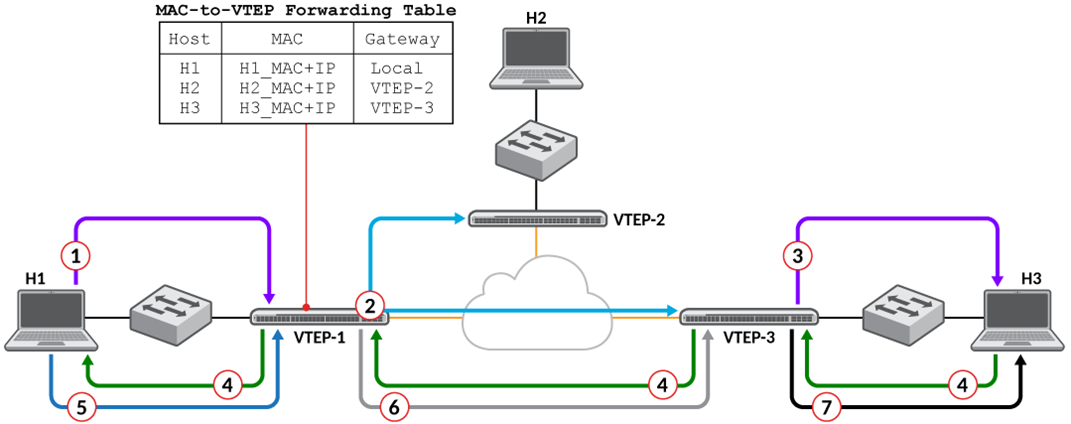
VXLAN Data Forwarding illustrates the sequence from a host initiating an ARP request to the destination host receiving the unicast packet. In a FastIron VXLAN implementation, the flow is:
- Host H1 broadcasts an ARP request to resolve H3’s MAC address. VTEP-1 receives the ARP frame on its access port.
- Using static ingress replication, VTEP-1 sends a unicast, VXLAN-encapsulated copy of the ARP request to every remote VTEP in the VNI’s full-mesh list (including VTEP-3).
- VTEP-3 receives the VXLAN packet, decapsulates it, and forwards the ARP request to H3 on its local access port.
- H3 responds with an ARP reply
containing its MAC address. VTEP-3 receives the reply and encapsulates it in a
VXLAN packet destined for VTEP-1.
VTEP-1 receives the VXLAN-encapsulated ARP reply, decapsulates it, and updates its MAC-to-VTEP mapping table to record that H3’s MAC is reachable via VTEP-3.
- With H3’s MAC address resolved, H1 sends a unicast Ethernet frame to H3.
- VTEP-1 encapsulates the frame in VXLAN and sends it directly to VTEP-3.
- VTEP-3 decapsulates the frame and delivers it to H3. Unicast communication is now established.
Inner Frame VLAN Tagging
At the encapsulating VTEP, the inner VLAN tag is removed before the frame is VXLAN-encapsulated and sent to the remote VTEP. At the destination VTEP, the frame is decapsulated and a VLAN is assigned based on the local VLAN-to-VNI mapping. The final tagging depends on the access port configuration:
- Tagged port: The VLAN tag is added after decapsulation and before the frame is forwarded.
- Untagged port: The frame is forwarded without a VLAN tag to the attached device.
Load Balancing in VXLAN Tunnels
To improve Equal-Cost Multi-Path (ECMP) or Link Aggregation Group (LAG) load distribution for VXLAN traffic, the encapsulating VTEP computes the UDP source port using a hash of Layer 2 and Layer 3 header fields from the original frame. This approach follows RFC 7348 and is supported by the FastIron VXLAN gateway.