MCT Peer as Intermediate Downstream Router
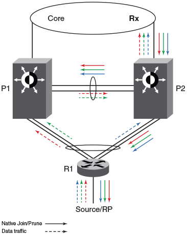
P1 and P2 are the MCT peers and are acting as downstream routers for R1. R1 is the
intermediate router.
P1, P2, and R1 are configured with PIM on the MCT VE interface. The RP and source are beyond R1.
Hello Exchange and Neighbor State
The RP acts and works as the upstream router.
Join or Prune Exchange and Mcache State
- The *,G joins come from the core to P2.
- P2 creates the *,G state with the uplink as the OIF by consuming the join state.
- Due to its *,G state, P2 originates a join towards the RP. This join is flooded on the MCT VLAN and R1 creates the *,G state.
- Upon receiving the join natively by way of ICL, P1 creates the *,G state and adds ICL as the OIF. As a special case, P1 will not include the *,G in the join it generates towards the RP because in this case the IIF is the CCEP and ICL is the only OIF and the remote CCEP is up. This is to avoid P1 pulling traffic from P2 unnecessarily on the ICL link because of P1 sending joins flooded on the VLAN and in turn P2 adds ICL as an OIF.
- R1 sends the join toward the RP and pulls the traffic. Because the OIF at R1 is a LAG, traffic pulled by R1 will be load-shared among the member links.
- Therefore traffic for S,G will reach only one of the MCT peers. Assuming the traffic reaches P2, the S,G state will be created on P2 and P2 will be forwarding the traffic.
- Assuming the traffic reaches P1, the traffic will be forwarded by way of the ICL to P2 and P2 will forward it to its OIF which is the link connecting to the core.