How MCT Works
The following figure shows a basic MCT configuration. The MCT originates at a single MCT-unaware server or switch and terminates at two MCT-aware devices.
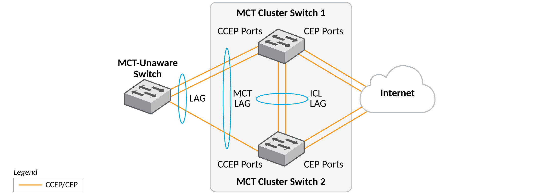
The MCT process involves the following processes:
- Sub-second failover occurs if a link, module, control plane, or device fails.
- Sub-second failover operates at the physical level.
- Layer 2 and Layer 3 forwarding (when using fast path forwarding) is done at the first hop regardless of the VRRP-E state.
- Load balancing is flow based (it does not involve VLANs sharing across network links).
- Resiliency is supported regardless of the traffic type (Layer 3, Layer 2, or non-IP legacy protocols).
- Interaction with Metro Ring Protocol (MRP) builds larger resilient Layer 2 domains.
- Device-level redundancy is provided in addition to link and modular redundancy.
- Traffic received from an ICL (Inter-Chassis Link) port is not forwarded to the Cluster Client Edge Ports (CCEPs) if the MCT peer device has the ability to reach the same cluster client.
- Traffic received from non-ICL ports is forwarded the same way as traffic from non-MCT devices.
- Known unicast traffic received on Cluster Edge Ports (CEPs) or ICL ports is forwarded to the destination port.
- For broadcast, unknown unicast, and multicast (BUM) traffic received on ICL ports, the forwarding behavior depends on the peer MCT device’s ability to reach the same client.
- Broadcast, unknown unicast, and multicast (BUM) traffic received from a CCEP is forwarded as usual, by default, flooding the entire VLAN.
- The cluster ID must be unique when there are multiple clusters interconnected in a topology. For example, in a cascaded Stage 2 MCT cluster, the cluster ID on a stage 1 pair of switches must be different from the cluster ID on a stage 2 pair of switches.