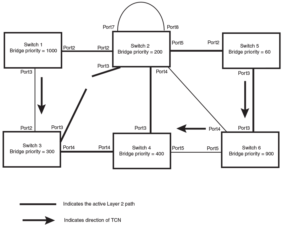
Propagation of Topology Change
The Topology Change state machine generates and propagates the topology change notification messages on each port. When a Root port or a Designated port goes into a forwarding state, the Topology Change state machine on those ports send a topology change notice (TCN) to all the bridges in the topology to propagate the topology change.
The TCN is sent in the RST BPDU that a port sends. Ports on other bridges in the topology then acknowledge the topology change once they receive the RST BPDU, and send the TCN to other bridges until all the bridges are informed of the topology change.
For example, Port3/Switch 2 in the following figure, fails. Port4/Switch 3 becomes the new root port. Port4/Switch 3 sends an RST BPDU with a TCN to Port4/Switch 4. To propagate the topology change, Port4/Switch 4 then starts a TCN timer on itself, on the bridge Root port, and on other ports on that bridge with a Designated role. Then Port3/Switch 4 sends RST BPDU with the TCN to Port4/Switch 2. (Note the new active Layer 2 path in the following figure.)
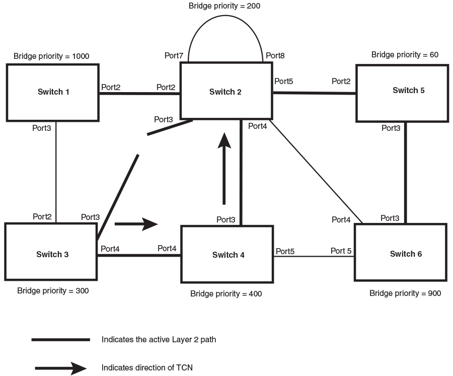
Switch 2 then starts the TCN timer on the Designated ports and sends RST BPDUs that contain the TCN as follows (Sending TCN to Bridges Connected to Switch 2):
- Port5/Switch 2 sends the TCN to Port2/Switch 5
- Port4/Switch 2 sends the TCN to Port4/Switch 6
- Port2/Switch 2 sends the TCN to Port2/Switch 1
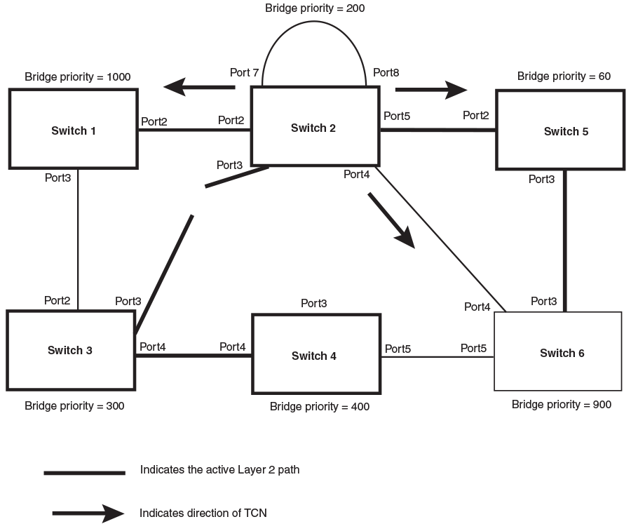
Then Switch 1, Switch 5, and Switch 6 send RST BPDUs that contain the TCN to Switch 3 and Switch 4 to complete the TCN propagation as shown in the following figure.