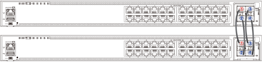
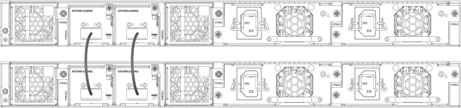
ICX 7450 Stacking Topologies
Up to 12 ICX 7450 units of any kind can be connected in a linear or ring topology. Valid-stack-ports are located on the rear panel as shown in the following figures. The valid-stack-port numbers are 1/3/1 and 1/4/1 (unit/slot/port); that is, they are the single port located in modules 3 and 4 of the ICX 7450 as shown.
The following figure shows the valid-stack-ports for the ICX 7450. These ports may also be used as data ports.
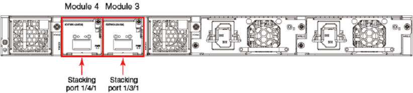
The following figure shows the 4X10GF module and port numbers.
write memory and the
reload commands.
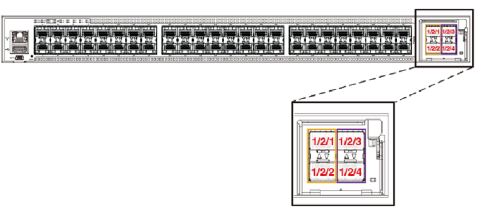
The following figure shows ICX 7450 units connected from 1 X 40-Gbps ports on the rear in a linear stack.
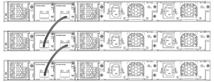
The following figure shows ICX 7450 units connected from 1 X 40-Gbps ports on the rear in a ring stack.
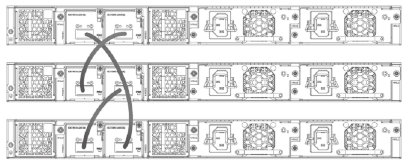
The following figure shows the ICX 7450 connected from the front in a ring using stacking trunks.
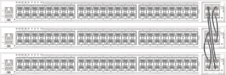
The following figure shows the ICX 7450 connected from the front in a linear stack using stacking trunks.
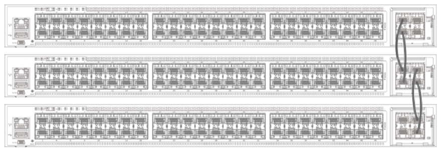
The following figures depict two-unit stacks with linear-topology trunks on the front and rear panel. ICX 7450-24P devices support this type of trunk, which improves redundancy and bandwidth. For more information, refer to Configuring Two-unit Stack Linear-topology Trunks.