Configuring DHCP and NAT Services on the Data Plane
The Data Plane delivers DHCP and NAT
services to automate client address assignment and manage address translation. DHCP
profiles
centralize shared parameters, such as domain name, DNS servers, lease defaults, and
vendor
options (Option43). DHCP pools apply these settings to specific VLANs or VNIs and
define the
subnet, mask, broadcast address, allocable ranges and exclusions, gateway or DNS overrides,
lease time, and Option43 association. Together, profiles and pools provide consistent
client
provisioning and predictable routing across deployments.
Creating a DHCP Profile
A DHCP profile defines global DHCP parameters—domain naming, DNS servers, and
lease defaults—and aggregates DHCP Option43 spaces and Hosts for later
association with one or more DHCP pools.
Note: A DHCP profile is required before you can create or
apply a DHCP pool.
- In the controller web UI, select .
- Click Create to open the Create DHCP Profile
dialog box and enter the information in the following fields:
- Profile Name: Identifier for the profile; referenced by pools. Use a unique, descriptive name to avoid ambiguity across Zones or Data Plane Groups.
- (Optional) Description: A brief description for the profile (for example, “Branch DHCP defaults”).
- (Optional) Domain Name: DNS suffix appended to client host names (DHCP option 15).
- (Optional) Primary DNS Server: DNS resolver IP address (DHCP option 6, first entry).
- (Optional) Secondary DNS Server: Backup resolver IP address (DHCP option 6, second entry).
- Lease Time: Default lease duration returned to clients unless overridden by pools or host bindings. A longer lease minimizes address reassignment; shorter leases accelerate reassignment in highly mobile environments. The default setting is 10 minutes.
- (Optional) Under DHCP Option43 Space,
click Create to define
vendor‑specific Type-Length-Values (TLVs) for clients that require
controller discovery or configuration. Note: Pools can bind one or more Option43 spaces so that APs or specialized clients receive vendor‑specific parameters in DHCP offers.
- In Space Name, enter a logical container name for a set of vendor TLVs; referenced by pools.
- (Optional) In Description, enter a brief description of the space purpose or usage (for example, “RUCKUS AP discovery”).
- In Option43 Sub Option, click Create to add sub‑options.
- In the Create Option43 Sub Option dialog box, enter the following then click OK to save the sub-options:
- Click OK to save the space configuration.
- (Optional) Under Hosts, click Create to add static host
bindings that override pool behavior for a specific client MAC. Complete the
following fields and click OK to add the host entry:Note: Static bindings ensure deterministic addressing for devices that must not change IP (for example, printers, payment terminals).
- Host: Name of the static binding (for example, “POS‑Terminal‑A”).
- (Optional) Description: Text briefly describing the host binding purpose or usage.
- MAC Address: Client identifier used to match the lease (Layer 2 key).
- (Optional) Broadcast Address: Broadcast address appropriate for the host’s fixed IP subnet.
- Fixed Address: Statically assigned IP address to this MAC (DHCP option 50 requested/assigned).
- Gateway: Default route for the host (DHCP option 3).
- (Optional) DNS Server: Resolver(s) dedicated for the host (DHCP option 6).
- (Optional) Domain Name: Domain suffix override (DHCP option 15).
- (Optional) Host Name: DHCP Host Name (option 12).
- (Optional) Lease Time: Lease override for this host. Default value is 10 seconds.
- Click OK to save the profile.
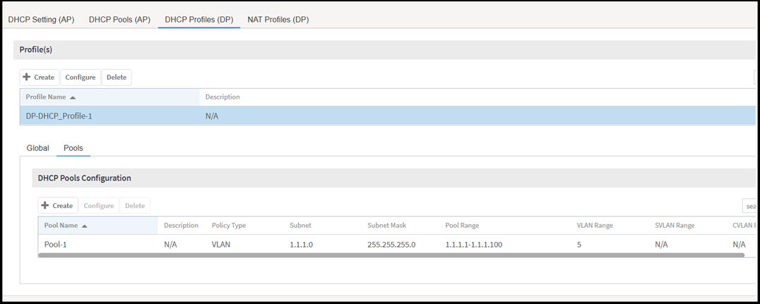
Creating a DHCP Pool Configuration
A DHCP pool configuration defines the assignable address ranges and
per‑subnet parameters (gateway, DNS, lease) that the Data Plane applies to clients
within a specific VLAN or VNI context.
Note: Pool address ranges must not overlap with other
pools serving the same broadcast domain.
- In the controller web UI, select .
- Select an existing DHCP profile from the list.
- Select the Pools tab and click Create to open the Create Pool Configuration dialog box.
- In General Options enter the following:
- In Policy Options, define the pool’s binding context with the
following options:
- Policy Type: Choose VLAN to bind the pool to Layer 2 VLAN(s), or VNI to bind to an overlay (VXLAN) context. This determines where clients are eligible to receive leases.
- VLAN Range: Enter one or more VLAN IDs using single
values or ranges (for example,
5or10–20). The pool applies to all listed VLANs. - QinQ VLAN: Toggle ON to enable double‑tagged VLAN operation for service‑provider edge use cases an enter the following information:
- In Assigning Options, enter subnet parameters:
- Subnet: Network address for the pool (for example,
172.16.100.0). - Subnet Mask: Mask (for example,
255.255.255.0) that defines the address space width. - Broadcast Address: Calculated broadcast address for the
subnet (for example,
172.16.100.255). - Pool
Range: Allocable address range(s), using a single IP or
start–end notation (notation syntax examples::
1.1.1.1or1.1.1.1–2.2.2.2). Use ranges inside the subnet; avoid including gateway or infrastructure IP addresses. - (Optional) Exclude Pool: List of IP addresses or ranges to reserve (not handed out), typically for servers, controllers, or statically addressed infrastructure.
- Primary Gateway: Default route (DHCP option 3) returned to clients.
- (Optional) Secondary Gateway: Backup gateway.
- Primary DNS Server: Resolver IP address returned as the first DNS server (DHCP option 6).
- (Optional) Secondary DNS Server: Backup resolver (second entry in option 6).
- Domain Name: DNS suffix (DHCP option 15) applied to clients for consistent FQDN resolution.
- (Optional) Host Name: DHCP Host Name (option 12). In most deployments, clients send their own host names; set only if policy requires.
- Lease Time: Duration of address allocation. Short leases aid rapid turnover (guest Wi‑Fi); longer leases reduce renewal traffic (IoT, printers).
- Subnet: Network address for the pool (for example,
- In Option43, click
Create to add
an Option43 space to this pool. The Create Option43 value dialog box opens for you to select a preconfigured space from the DHCP Profile configuration. Optionally, you can click the
 icon to create a new option 43 entry as
explained in step 3 of Creating a DHCP Profile.
- Click OK to save the pool configuration.
Creating a NAT Profile
Note: A NAT profile is required before you can
create or apply a NAT pool.
- In the controller web UI, select .
- Click Create to open the Create NAT Profile
dialog box and enter the information in the following fields:
- Profile Name: Identifier for the profile; referenced by pools. Use a unique, descriptive name to avoid ambiguity across Zones or Data Plane Groups.
- (Optional) Description: A brief description of the profile purpose or usage (for example, “Branch NAT”).
- Subnet: The
public NAT subnet from which translated addresses will be allocated.
This must be the network address of the subnet, not a single host
(for example,
17.16.200.0). NAT pools draw public IP addresses from this subnet. - Prefix: Subnet prefix length (for example, 24 for a /24 network). This defines the size of the public NAT subnet.
- (Optional) Public VLAN: Optional VLAN ID for tagging or untagging traffic on the public/outbound interface. Use this when the upstream network requires VLAN encapsulation for NAT traffic.
- Gateway: The next hop for outbound traffic after NAT translation. This gateway must belong to the same public subnet because the Data Plane uses it to route translated packets toward the upstream network or Internet.
- Click OK to save the profile.
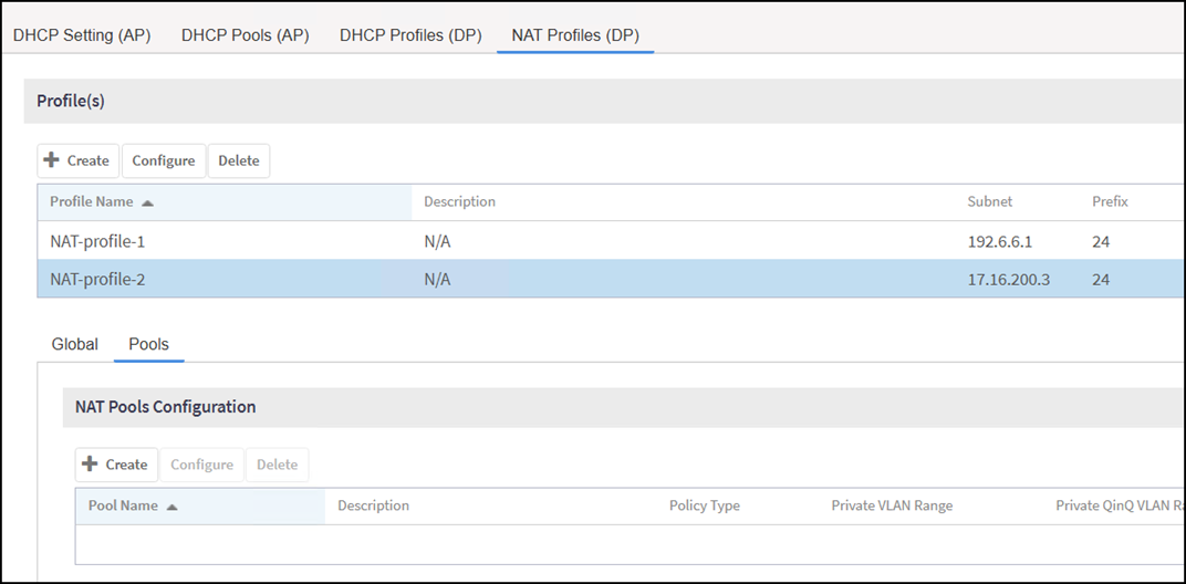
Creating a NAT Pool Configuration
A NAT pool configuration
defines the public address resources and mapping parameters that the Data Plane uses
to translate traffic from internal subnets within a specific VLAN or VNI context.
A
NAT profile is required before you can create or apply a NAT pool.
Note: NAT pool address ranges must not overlap with other
NAT pools serving the same outbound interface or VLAN context. Overlapping
ranges can cause unpredictable translation behavior and session
failures.
- In the controller web UI, select .
- Select an existing NAT profile from the list.
- Select the Pools tab and click Create to open the Create Pool Configuration dialog box.
- In General Options enter the following:
- In Policy Options, define the pool’s binding context with the
Policy Type, choose one of the
following:
- VNI: Bind the pool to an overlay (VXLAN) context.
- VLAN:
Bind the pool to one or more Layer 2 VLANs. If QinQ is required,
complete the SVLAN and CVLAN fields.
- Private VLAN Range: Enter one or more VLAN IDs
using single values or ranges (for example,
5or10–20) and click Add to add the entry. Continue to add VLAN(s) or VLAN range(s) as required. - Private QinQ VLAN Range: If your deployment requires double-tagged VLAN operation (service-provider edge), complete the following fields and click Add:
- Private VLAN Range: Enter one or more VLAN IDs
using single values or ranges (for example,
- In Translation Options, review the following prepopulated
parameters from the associated NAT Profile (these values cannot be
edited here):
- Subnet: Public NAT subnet defined in the profile.
- Prefix: Subnet prefix length inherited from the profile.
- Public VLAN: VLAN ID for the public-facing interface, as configured in the profile.
- Gateway: Next hop for outbound traffic after NAT translation, inherited from the profile.
Note: These values are inherited from the NAT Profile and cannot be changed at the pool level.Then enter the following pool-specific parameters:
- Port
Range: Define the range of ports for Port Address
Translation (PAT). Example:
10000–20000. -
Public Address Range: Enter one or more public IP addresses or ranges within the configured public subnet (for example,
17.16.200.10or17.16.200.10–17.16.200.50) and click Add to add the entry. Continue to add additional entries as required.Note: Do not duplicate public addresses across pools or with the NAT Profile or Data Plane interface IP addresses.
- Click OK to save the pool configuration.