Precision Time Protocol Overview
Precision Time Protocol (PTP) is a two-way time transfer protocol that was introduced in the IEEE-1588-2002 standard, which was revised by a new version called PTPv2 that is addressed by IEEE-1588v2-2008.
In Ethernet networks, the switches forward Ethernet frames to the connected devices and some of the frames are subjected to store-and-forward conditions. This causes the switches to delay in sending those packets and to lose synchronization. PTP has been developed to ensure clock synchronization in a packet-based network like an Ethernet network and to correct the latency and time delays. Unlike Network Time Protocol (NTP), the PTP clock devices will stamp the precise time that the synchronization messages spend in each device.
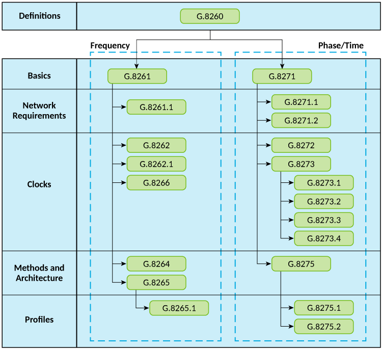
The following figure provides a summary of the standards within the ITU-T SG15/Q13 (Telecommunication Standardization Sector of the International Telecommunications Union) that are related to frequency and phase or time delivery using PTP. These standards can be divided into two major groups:
The G.8260 model (for timing and synchronization in packet networks) is applicable to both the groups.
The following figure defines the network reference model provided in ITU-T G.8271. This is used to define time and phase synchronization performance objectives. The following model defines reference points for the timing measurements with respect to a common time reference such as GPS time.
=GUID-A791D594-C08B-4360-AA13-9763FFBA8E51=2=en-US=Low.png)
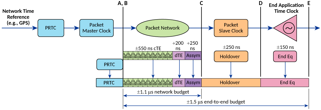
The following figure is an example that shows the end-to-end time error network budget for an LTE-TDD application.