MCT Data Flow
MCT can be deployed in a single-level configuration that includes two MCT cluster devices or in a cascading configuration, where a pair of MCT cluster devices operate as switches, and another pair of cluster devices operates as routers. Refer to Single-Level MCT Configuration Example for a single-level illustration and configuration example, and Two-Level MCT Configuration Example for a two-level or cascading configuration example.
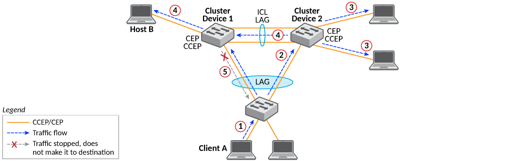
Broadcast, Unknown Unicast, and Multicast Traffic from a Client Through a CCEP
- Traffic originates at the client.
- Because the link between the client switch and the MCT cluster is a trunk, the traffic travels over one physical link. In the example shown in the following figure, the traffic travels over the link toward Cluster Device 2. The traffic enters the MCT cluster through the CCEP of Cluster Device 2.
- The traffic is sent to any local CEPs and CCEPs.
- It passes to the peer cluster device over the ICL link, where it is sent to the peer device’s local CEPs.
- Traffic does not pass back down to the client through the CCEP.
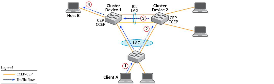
Unicast Traffic from a Client Through a CCEP to a CEP
- Traffic originates at the client.
- Because the link between the client switch and the MCT cluster is a trunk, the traffic travels over one physical link. As shown in the following figure, the traffic travels over the link toward Cluster Device 2. The traffic enters the MCT cluster through the CCEP of Cluster Device 2.
- Depending on the destination, the traffic may pass over the ICL link to the other cluster device. In the following figure, the destination is on Cluster Device 1, so the traffic is forwarded out to the ICL port.
- The traffic passes out to the destination.
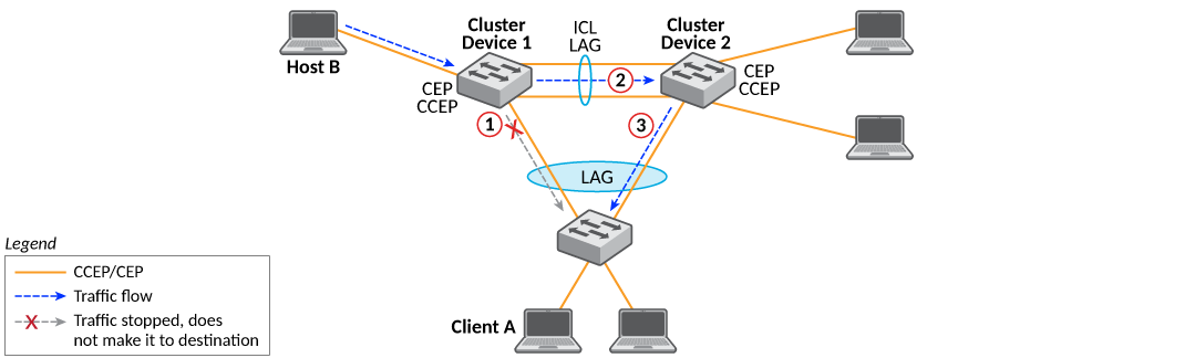
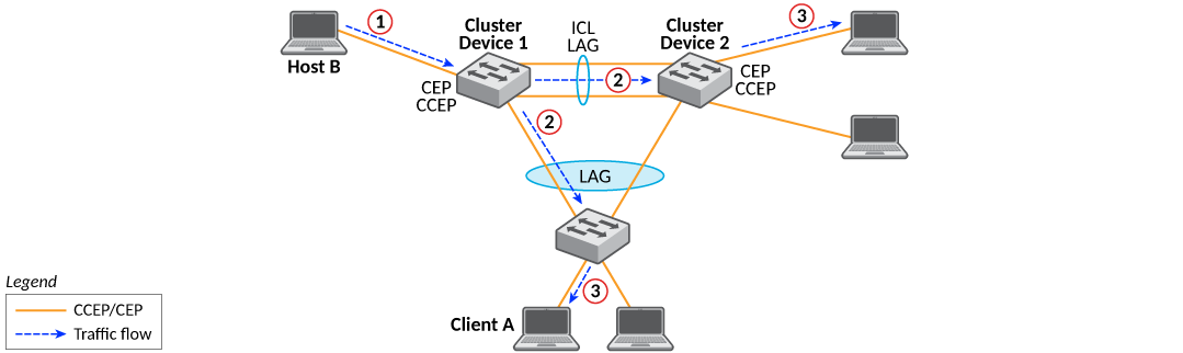
Broadcast, Unknown Unicast, and Multicast Traffic from a Client Through a CEP
- Traffic originates at the client and enters one of the MCT cluster devices through a CEP.
- As shown in the following figure, the traffic is sent to the peer cluster device through the ICL link.
- The traffic is sent to any local CCEPs and CEPs and subsequently delivered to the end hosts.
- Once traffic is received on the peer cluster device, it will be sent to its local CEPs.
- Traffic is not duplicated in the other members of the LAG to the client switch.
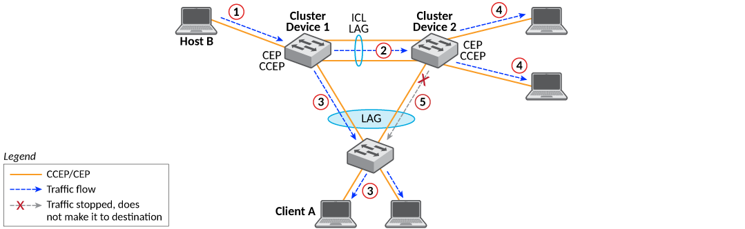
Unicast Traffic from a Client Through a CEP to Another CEP or a CCEP
- Traffic originates at the client and enters one of the cluster devices through the CEP, as shown in the following figure.
- Depending on the destination, the traffic may pass over the ICL link to the other cluster device, or it may be sent to a local CCEP.
- The traffic passes out to the destination.
Port Failure on the Cluster Device
- A CCEP on the Cluster Device 1 fails.
- As shown in the following figure, the traffic is automatically redirected to the other MCT cluster device over the ICL.
- The traffic passes to its destination through CCEPs.