Layer 2 Port-Based VLANs
On all RUCKUS ICX devices, you can configure port-based VLANs. A port-based VLAN is a subset of ports on a RUCKUS ICX device that constitutes a Layer 2 broadcast domain.
By default, all the ports on a RUCKUS ICX device are members of the default VLAN. Thus, all the ports on the device constitute a single Layer 2 broadcast domain.
You can configure multiple port-based VLANs. You can configure up to 4094 port-based VLANs on a Layer 2 switch or a Layer 3 switch. On both device types, valid VLAN IDs are 1 - 4095. You can configure up to the maximum number of VLANs within that ID range.
The following behaviors apply to VLANs:
- By default, interfaces are untagged members of the default VLAN.
- When you configure an interface as untagged member of a non-default VLAN, that interface will be moved from the default VLAN to the configured VLAN.
- When you configure an interface as a tagged member of a non-default VLAN, the untagged VLAN membership of the interface will not be modified, be it default-VLAN or non-default VLAN. You can configure default VLAN port membership.
- You can remove untagged membership of an interface using the
no untagged ethernetcommand within the default VLAN node. - An interface should be a member of at least one VLAN at any given time.
- An interface will be moved to the default VLAN when the last non-default VLAN is removed on that interface (tagged or untagged).
- When an untagged membership of an interface is removed from a non-default VLAN, the
interface will be added back to the default VLAN as an untagged interface.
Note: An untagged interface can be configured as tagged in other user VLANs, and a tagged interface can be configured as untagged in a default VLAN or in non-default VLANs.
Because each port-based VLAN is a separate Layer 2 broadcast domain, each VLAN can be configured to run a separate instance of the Spanning Tree Protocol (STP). Layer 2 traffic is bridged within a port-based VLAN, and Layer 2 broadcasts are sent to all the ports within the VLAN.
Configuring Port-Based VLANs
Port-based VLANs allow you to provide separate spanning tree protocol (STP) domains or broadcast domains on a port-by-port basis.
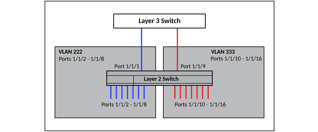
The following figure shows a simple port-based VLAN configuration using a single RUCKUS Layer 2 switch. All ports within each VLAN are untagged. One untagged port within each VLAN is used to connect the Layer 2 switch to a Layer 3 switch for Layer 3 connectivity between the two port-based VLANs.
The following figure shows a more complex port-based VLAN configuration using multiple Layer 2 switches and IEEE 802.1Q VLAN tagging. One untagged port within each port-based VLAN on Device-A connects each broadcast domain VLAN to the router for Layer 3 forwarding between broadcast domains (inter-VLAN routing). The STP priority is configured to force Device-A to be the root bridge for VLANs RED and BLUE. The STP priority on Device-B is configured so that Device-B is the root bridge for VLANs GREEN and BROWN.
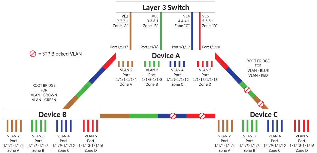
To configure the port-based VLANs on the Layer 2 switches shown in More Complex Port-Based VLAN, use the procedures found in Configuring Port-Based VLANs on Device-A, , and .