Bridges and Bridge Port Roles
A bridge in an IEEE 802.1w rapid spanning tree topology is assigned as the root bridge if it has the highest priority (lowest bridge identifier) in the topology. Other bridges are referred to as non-root bridges.
Unique roles are assigned to ports on the root and non-root bridges. Role assignments are based on the following information contained in the Rapid Spanning Tree Bridge Packet Data Unit (RST BPDU):
The IEEE 802.1w algorithm uses this information to determine if the RST BPDU received by a port is superior to the RST BPDU that the port transmits. The two values are compared in the order as given above, starting with the Root bridge ID. The RST BPDU with a lower value is considered superior. The superiority and inferiority of the RST BPDU is used to assign a role to a port.
If the value of the received RST BPDU is the same as that of the transmitted RST BPDU, then the port IDs in the RST BPDUs are compared. The RST BPDU with the lower port ID is superior. Port roles are then calculated appropriately.
The port role is included in the BPDU that it transmits. The BPDU transmitted by an IEEE 802.1w port is referred to as an RST BPDU, while it is operating in IEEE 802.1w mode.
Ports can have one of the following roles:
- Root: Provides the lowest cost path to the root bridge from a specific bridge
- Designated: Provides the lowest cost path to the root bridge from a LAN to which it is connected
- Alternate: Provides an alternate path to the root bridge when the root port goes down
- Backup: Provides a backup to the LAN when the Designated port goes down
- Disabled: Has no role in the topology
Assignment of Port Roles
At system start-up, all IEEE 802.1w-enabled bridge ports assume a Designated role. Once start-up is complete, the IEEE 802.1w algorithm calculates the superiority or inferiority of the RST BPDU that is received and transmitted on a port.
On a root bridge, each port is assigned a Designated port role, except for ports on the same bridge that are physically connected together. In these types of ports, the port that receives the superior RST BPDU becomes the Backup port, while the other port becomes the Designated port.
On non-root bridges, ports are assigned as follows:
- The port that receives the RST BPDU with the lowest path cost from the root bridge becomes the Root port .
- If two ports on the same bridge are physically connected, the port that receives the superior RST BPDU becomes the Backup port, while the other port becomes the Designated port.
- If a non-root bridge already has a Root port, then the port that receives an RST BPDU that is superior to those it can transmit becomes the Alternate port.
- If the RST BPDU that a port receives is inferior to the RST BPDUs it transmits, then the port becomes a Designated port.
- If the port is down or if IEEE 802.1w is disabled on the port, that port is given the role of Disabled port. Disabled ports have no role in the topology. However, if IEEE 802.1w is enabled on a port with a link down and the link of that port comes up, then that port assumes one of the following port roles: Root, Designated, Alternate, or Backup.
The following example (Simple IEEE 802.1w Topology) explains role assignments in a simple RSTP topology.
The topology in the following figure contains four bridges. Switch 1 is the root bridge since it has the lowest bridge priority. Switch 2 through Switch 4 are non-root bridges.
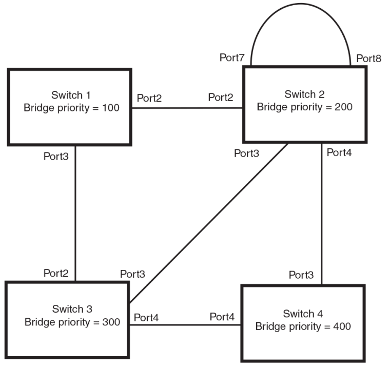
Assignment of Ports on Switch 1
All ports on Switch 1, the root bridge, are assigned Designated port roles.
Assignment of Ports on Switch 2
Port2 on Switch 2 directly connects to the root bridge; therefore, Port2 is the Root port.
The bridge priority value on Switch 2 is superior to that of Switch 3 and Switch 4; therefore, the ports on Switch 2 that connect to Switch 3 and Switch 4 are given the Designated port role.
Furthermore, Port7 and Port8 on Switch 2 are physically connected. The RST BPDUs transmitted by Port7 are superior to those Port8 transmits. Therefore, Port8 is the Backup port and Port7 is the Designated port.
Assignment of Ports on Switch 3
Port2 on Switch 3 directly connects to the Designated port on the root bridge; therefore, it assumes the Root port role.
The root path cost of the RST BPDUs received on Port4/Switch 3 is inferior to the RST BPDUs transmitted by the port; therefore, Port4/Switch 3 becomes the Designated port.
Similarly Switch 3 has a bridge priority value inferior to Switch 2. Port3 on Switch 3 connects to Port 3 on Switch 2. This port will be given the Alternate port role, since a Root port is already established on this bridge.
Assignment of Ports on Switch 4
Switch 4 is not directly connected to the root bridge. It has two ports with superior incoming RST BPDUs from two separate LANs: Port3 and Port4. The RST BPDUs received on Port3 are superior to the RST BPDUs received on port 4; therefore, Port3 becomes the Root port and Port4 becomes the Alternate port.