Configuring RUCKUS Edge Cluster Ports and IP Settings
- From the RUCKUS One navigation
bar, select .This displays a list of the RUCKUS Edge clusters and devices added to the RUCKUS One tenant account.
- Select the checkbox beside the
cluster and click Run
Cluster & RUCKUS Edge configuration wizard.This displays the Cluster & RUCKUS Edge Configuration Wizard page.Note: RUCKUS recommends using the Cluster & RUCKUS Edge configuration wizard to configure these settings.
- Select LAG, Port, Sub-Interface
& Virtual IP Settings and click Next.The Cluster & RUCKUS Edge Configuration Wizard page is displayed.
- Within the wizard, configure the
following:
- LAG Settings
- Port General Settings
- Sub-interface Settings
- Dual WAN SettingsNote: Dual WAN Settings apply only to single-node clusters.
- Cluster Virtual IP
Alternatively, you can configure LAG and Ports using the following procedure for each RUCKUS Edge device in a cluster:- From the RUCKUS One navigation bar, click on .
This displays the RUCKUS Edge devices.
- Select an Edge cluster
and click the
 icon to expand and view the associated
devices.
- Click on the device name. This displays the Overview page.
- From the Overview page:
- Proceed with Port General Settings or LAG Settings.
LAG Settings
- Click Add LAG to create a new LAG for the first node in the cluster.
- Enter the following details to add a LAG to the RUCKUS Edge
device.Note: Adding ports with existing configuration to a LAG will prompt you with a warning message stating that the existing configuration will be deleted from the ports.
- LAG Name: Select a name for the LAG from the drop-down list. The LAG name is a numeric value from 0 through 3. After the LAG is created, you cannot edit the LAG name.
- Description: Enter a meaningful, short description about the LAG.
- LAG Type: The default type is LACP (Dynamic) as RUCKUS Edge does not support static LAG.
- Mode: Click
the drop-down list and select the mode of the LAG. There are two
modes:
- Active: Always initiates Link Aggregation Control Protocol (LACP) and Protocol Data Unit (PDU) to the peer. This is the default mode for RUCKUS Edge LACP LAG.
- Passive: Never initiates any LACP exchange on its own. It responds only after receiving LACP and PDU messages from the peer/partner device. Hence, both peers cannot be in passive mode. At least one of the peers should be configured in active mode.
- Timeout: Time
interval indicates how long the LACP should wait before declaring
the partner as down. This interval also defines the rate at which
LACP hello packets are exchanged among the peers. There are two
types of timeout.
- Long: The value of this timeout is 90 seconds. Hello packets are transmitted every 30 seconds. After 3 misses (3*30s = 90 seconds), the peer information is flushed and the LACP state is declared as down.
- Short: The value of this timeout is 3 seconds. Hello packets are transmitted every 1 second. After 3 misses (3*1s = 3 seconds), the peer information is flushed. This is the default timeout for RUCKUS Edge LACP LAG.
- Select LAG
Members: A physical port associated with a LAG interface is
a LAG member. To associate LAG members, select the ports to be
members of this LAG. The Port
Enabled option beside the respective port is enabled
by default. Toggle the button to disable the port. Selecting
Port1 enables Access
port and Port2
enables Core port option. Select both ports Port1
and Port2 if Access and Core separation is not
intended.
Note: Access/Core separation is part of the SD-LAN feature. Refer Software Defined Local Area Network, for more information.
- Port
Type - Select the type of port from the drop-down
list.
Note: A maximum of two WAN interfaces are allowed.
Port Type Configuration
- Click Add.
- Click the sub-tab for the
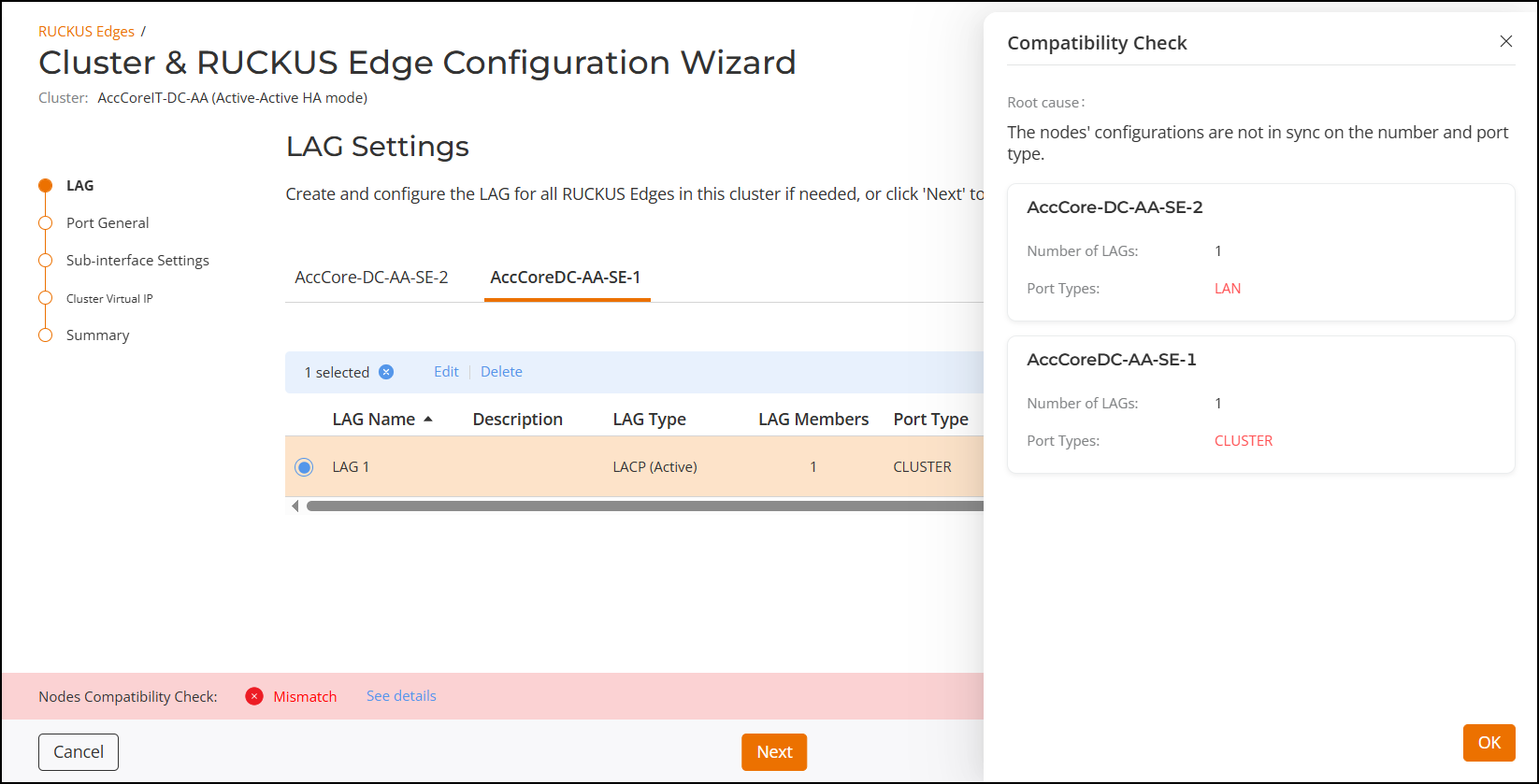
second node in the cluster, then repeat and to add a LAG to the second node.RUCKUS One performs a compatibility check of the configurations on each node. If a mismatch is detected, it displays a warning message labeled Mismatch. You can click on the See Details option to view the root cause and specifics of the mismatch to quickly identify the discrepancies.
You can Edit or Delete the offending LAG by selecting the checkbox adjacent to the LAG. After the mismatches are resolved, the compatibility check result changes to Pass.
- Click Next.
Port General Settings
- Within each port sub-tab,
configure the following details:
- Description - Enter a short description to identify the port.
- Port
Type - Select the type of port from the drop-down
list.
Note: A maximum of two WAN interfaces are allowed.
Port Type Configuration
- Click Next.
Sub-interface Settings
- From the Sub-interface Settings page, select the required port tab and click Add Sub-interface.
- Configure the following
details:
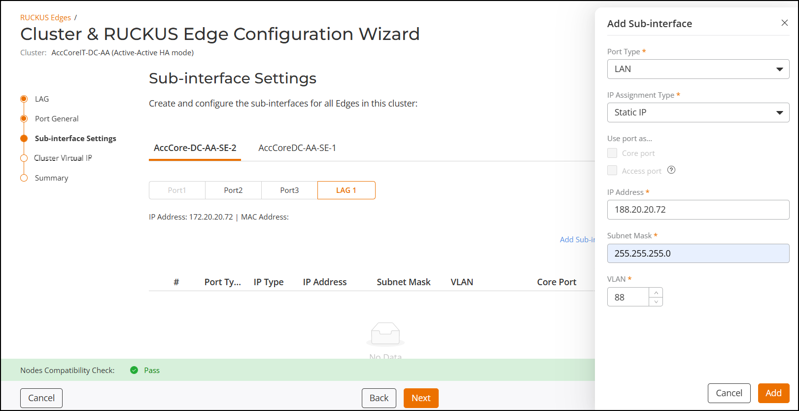
- Port Type - Select the port type from the drop-down list.
- IP Assignment Type - By default, the IP assignment type is DHCP, however, to manually configure the ports, select Static IP from the drop-down list and enter the IP Address and Subnet Mask.
- Use port
as: Select the required checkboxes. Options include
Core
port and Access
port.
Hover over the
 icon next to Access
port and click See the
compatibility requirements to check the
Compatibility Requirement.
If any port is selected as WAN, Access port, or Core port in the previous sections, these options will not be available to the sub-interfaces. For more information refer to Software Defined Local Area Network.
- VLAN: Enter a VLAN ID. Allowed values are 1 through 4094.
- After entering all the
details in the respective fields, click Add.The sub-interface settings are displayed on the screen.
- Repeat to configure other sub-interfaces.
- Click Next.The Dual WAN Settings page is displayed.
Dual WAN Settings
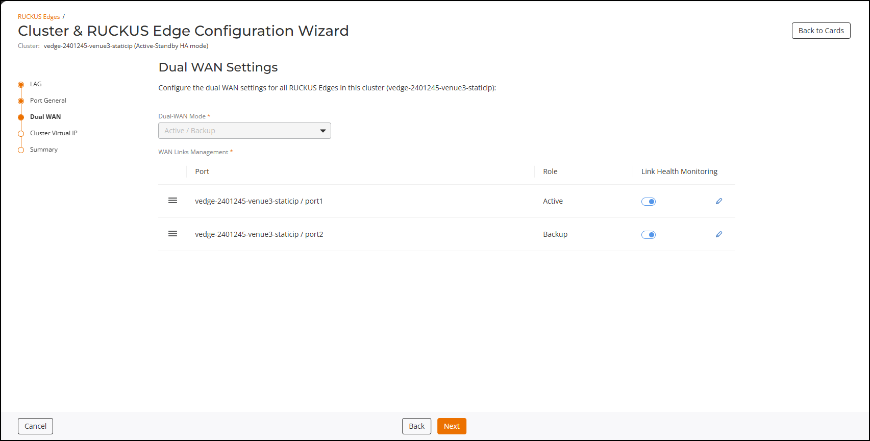
 icon beside the required port, then drag and drop it to the desired order.
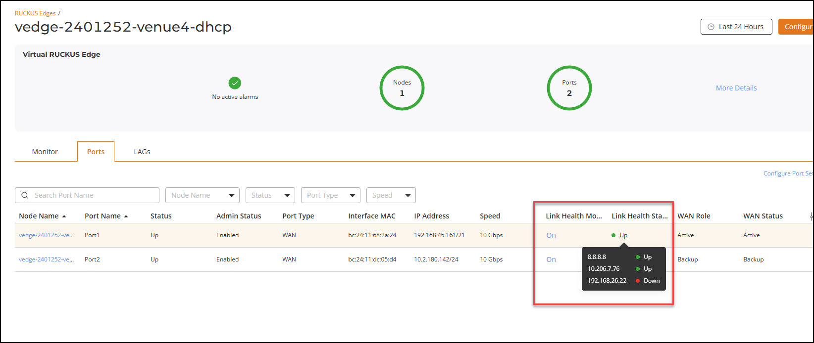
- Click the Link Health Monitoring toggle to enable or disable link health monitoring. If disabled, then link failover cannot occur if the link fails.
- Click the
 icon to configure the link health monitoring settings for the port. The
Link Health Monitoring sidebar is displayed.
- Configure the following for
both ports:
- Protocol: The ICMP (Ping) option is selected by default.
- Target IP Addresses: Click Add Target and enter the destination IP address. A maximum of three IP addresses can be added.
- Failure Condition: Choose one of the following conditions:
- Check Interval: Enter the time interval, in seconds, for performing failover checks. Default value: 3 seconds.
- Mark link as DOWN after: Enter the number of retries before confirming failure. Range: 2-10; default value: 3.
- Mark link as UP after: Enter the number of retries before confirming link restoration. Range: 2-10; default value: 3.
- Click Save to apply the failover configuration.
- Click Next.The Cluster Virtual IP page is displayed.
Cluster Virtual IP
- Click Select Interface.The Select Interfaces sidebar is displayed.
- Select the interface from the Select Port drop-down.
- Click OK.
- For Virtual IP Address, enter the virtual IP address for the RUCKUS Edge cluster.
- For Failover
Settings, slide the marker on the HA Timeout
timeline bar to adjust the amount of time allowed to elapse before
triggering a failover.Note: An HA failover time of 6 seconds or longer is recommended for RUCKUS Edge use-cases. A timer set to less than this is very aggressive and could potentially cause VRRP issues in some networks. HA timeout refers to the time period within which a node must receive a periodic heartbeat signal from the active node. If the timer expires prior to receiving a heartbeat signal, then the system initiates the failover process to select the next active node and maintain system functionality.
- Click Next.The Summary page is displayed.
- Review the configuration and click one of the following: