How ISSU Works When Upgrading a Campus Fabric (SPX) System
The following section describes the checks and the upgrade sequence for an SPX system in the typical topology shown below. For a step-by-step procedure on performing an ISSU, refer to Upgrading an SPX System with ISSU.
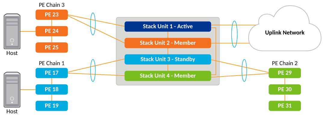
After you have downloaded release software as described in
Initial steps and
The upgrade process, you can check the sequence in which stack units will be upgraded using the
show issu sequence command.
The following example displays
show issu sequence command output for the Campus Fabric (SPX) topology shown above and indicates the
sequence in which CB units and their associated PE units will be upgraded. PE units
are upgraded along with their associated CB units. This association of PE units to
CB units is computed automatically.
device# show issu sequence
Stack units will be upgraded in the following order
ID     Type              Role
3      ICX7750-48XGC     standby
   17  ICX7450-32ZP      spx-pe
   18  ICX7150-48ZP      spx-pe
   19  ICX7150-48        spx-pe
2      ICX7750-20QXG     member
   23  ICX7450-32ZP      spx-pe
   24  ICX7150-48ZP      spx-pe
   25  ICX7150-48        spx-pe
4      ICX7750-48XGF     member
   29  ICX7450-32ZP      spx-pe
   30  ICX7150-48ZP      spx-pe
   31  ICX7150-48        spx-pe
1      ICX7750-48XGF     active

PEs 17, 18, 19 are associated with CB unit 3 for upgrade.
PEs 23, 24, 25 are associated with CB unit 2 for upgrade.
PEs 29, 30, 31 are associated with CB unit 4 for upgrade.
As reflected in
show issu sequence output, the system responds to the
issu command in the following ways:
- Unit 3, the standby controller, is reloaded with the new image, along with associated PEs 17, 18, and 19.
- Once the standby controller and associated PEs join the SPX system, member units from the standby controller to the active controller (unit 2 in the previous figure) reload from the new image. Along with CB unit 2, associated PEs 23, 24, and 25 are also upgraded.
- All members from the standby controller to the active controller in the other direction (unit 4) reload from the new image. Along with unit 4, associated PEs 29, 30, and 31 are also upgraded.
- Once all member units and the standby controller are reloaded with the new image, the active controller triggers a switchover, in which the old standby controller (unit 3) becomes the new active controller, and the old active controller (unit 1) becomes the new standby controller.
- The new active controller (unit 3) reloads the old active controller (unit 1) with the new image. If there are any PEs attached to unit 3 that are not yet upgraded (none in this example), they are upgraded next.
- Once the old active controller (unit 1) comes up as a member unit and rejoins the
SPX system, standby controller election occurs, and the SPX system becomes fully functional
with the upgraded image.
Note: If the stack unit configurations include priority settings, a final switchover occurs to ensure that the unit with the highest priority becomes the active controller.