Campus Fabric topology overview
The CB stack consists of a maximum of 4 ICX 7650 units connected in a linear or ring topology. PE units are specially configured ICX 7450, ICX 7250, or ICX 7150 units that are connected to the CB. The PE units can be connected to each other over a single SPX port or LAG to form a PE chain or ring. The PE chain or ring can contain a combination of ICX 7150, ICX 7250, or ICX 7450 units.
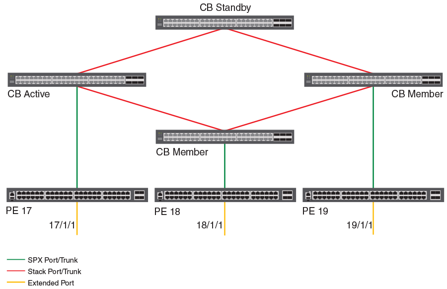
In the following figure, four ICX 7650 units are configured in a ring stack form the CB. Three of the CB units are connected to PE units (SPX 17, 18, and 19).
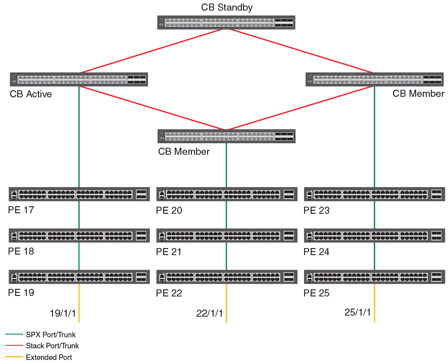
In the following figure, three of the ICX 7650 CB units are connected to PE units (labeled as SPX units). The directly connected PE units (cascade PEs) are connected to additional PE units to form an SPX chain, also referred to as a PE chain. Each SPX chain in the figure contains three PE units.
Rules governing Campus Fabric topology
A Campus Fabric domain can be discovered and automatically configured in some cases and interactively configured in other cases. Understanding the rules that apply to supported topologies will help you configure or modify the Campus Fabric domain.
The following rules apply to supported Campus Fabric topologies:
- A PE unit can have a maximum of two SPX port or SPX LAG connections.
- CB units can have many SPX ports and LAGs.
- An SPX LAG can contain from 2 to 16 ports. For ICX 7650 CB units, ICX 7450 PE units, and ICX 7250 PE units, the maximum number of ports in an SPX LAG is 16 ports. For PE units that are ICX7150 devices, the maximum ports in an SPX LAG is 8 ports.
- Both ends of a link between a CB and a PE or between two PE units must be an SPX port or an SPX LAG.
- The CB must be able to reach any PE unit in a PE chain using the single SPX port or LAG. The CB must be able to reach any PE unit in a ring using either of the two SPX ports or LAGs.
- The maximum number of PE units in a chain or ring is six.
- An SPX LAG cannot link to multiple SPX ports or LAGs.
- A single PE unit cannot form a ring. An SPX LAG between the PE unit and the CB is recommended instead. If the system detects a single PE ring, one of the SPX ports or LAGs will be disabled to break the ring.
Supported CB-PE LAG topologies
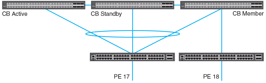
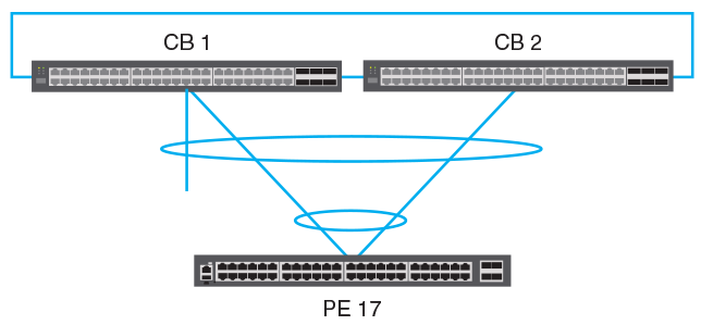
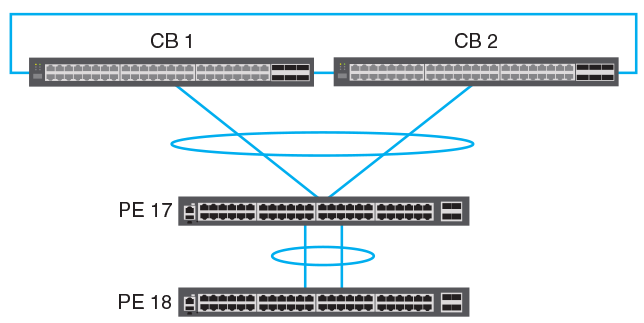
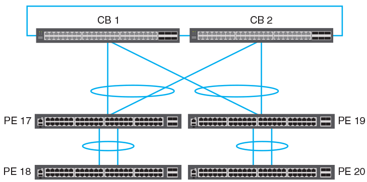
One PE unit can be connected to more than one CB unit when the connection is configured as a single LAG. If one of the connected units in the CB fails, the PE unit still maintains a connection to the CB. In the following figure, SPX 17 is connected to more than one CB unit by a single LAG.
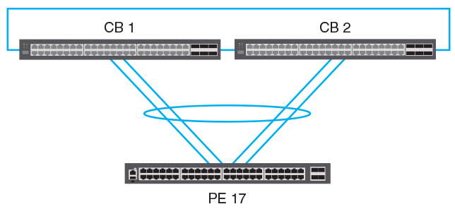
Other supported LAG topologies are shown in the following figures.
CB-PE shared LAG containing an unattached data link
spx-lag or
multi-spx-lag command to correct the configuration.
Supported PE ring topology
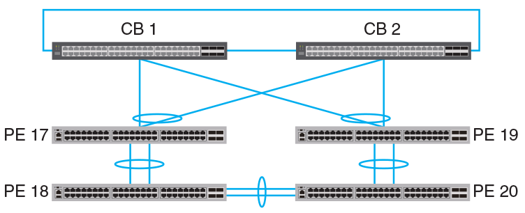
A redundant SPX link can be connected from a CB unit to the edge PE of an existing PE chain or between two edge PEs of two existing PE chains to form a PE ring. You can combine ICX 7150, ICX 7250, and ICX 7450 devices in a PE ring just as you can in a PE chain. The following figure represents the allowable PE ring topology. When the ring is active, traffic is generally load-balanced over the two existing SPX links.
PE ring topology limitations
Consider the following points before configuring a ring topology:
- SPX links can be connected to the first (cascade) PE or the last PE in a PE chain. However, a PE ring cannot be formed by connecting an SPX link between two PEs of an existing chain.
- PE ring topology with one PE unit is not supported; a PE ring requires at least two PE units.
- PE ring topology supports a maximum of six PE units.
Traffic flow in a PE ring topology
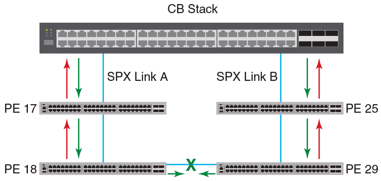
In the following figure, the red arrow represents upstream traffic, that is, traffic originating through a PE extended port. Upstream traffic is sent to the CB for lookup and replication. The green arrow represents downstream traffic, that is, the traffic exiting through a PE extended port. The CB replicates downstream traffic on one or both of the SPX links, depending on the type of traffic.
The green 'X' between PE 18 and PE 29 illustrates the logical block in the active ring. The ring remains up, but downstream traffic is intentionally dropped at this point to prevent the traffic from traveling back to the CB through a redundant SPX link. If the ring topology changes, the logical block may also move to a new point between two other PE units.
When the ring is active, each PE unit is mapped to one of the SPX links, and any known unicast traffic that flows through the PE uses the same SPX link until the ring breaks or the ring topology changes. If the ring breaks and the mapped SPX link is no longer reachable, a PE unit is remapped to the alternate SPX link, assuming it is reachable. (Traffic is lost only until reconvergence is complete.)
For multicast or BUM traffic, each PE unit is mapped to one of the SPX links to carry upstream traffic. All traffic downstream is carried on both SPX links. This duplication avoids remapping the PE unit when the ring breaks and allows for faster reconvergence following failover.
Best practices for PE ring configuration
There are two suggested methods for forming a PE ring from two PE chains. In both methods, you must form an SPX link by configuring an SPX port or SPX LAG on both ends of a connection and then physically link the cables.
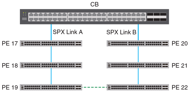
The first method is to connect the edge PEs of two linear chains through an SPX link as shown in the following figure.
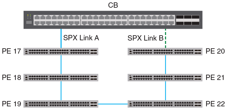
The second suggested method for creating a PE ring is to form an SPX link between the edge PE of an existing chain and the CB SPX cascade port as shown in the following figure.
It is not necessary to configure a ring explicitly. Once you have connected the PEs to form a physical ring, the system is able to generate the correct pe-id configuration under spx cb-configure.
Once the topology learns about the PE ring, you can verify its presence with the
show spx command. You can then check
show running-config command output for
pe-id configuration details for the ring (for example, pe-id CB-port 1 ID1 ID2 ... CB-port
2).
show spx command does.
To avoid losing the configuration during a CB reboot, save it by executing the
write memory command.