Campus Fabric data path
To understand packet flow in a Campus Fabric system, consider what happens when one host pings another through the Campus Fabric network. In the following figure, both hosts are connected to the same PE unit.
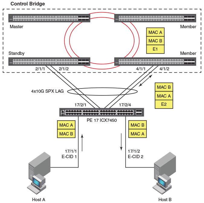
The following steps describe the series of events required for Host A to communicate with Host B.
- Host A pings Host B.
- The packet sent by Host A travels over port 17/1/1 to access PE unit 17, where an E-tag with the E-CID 1 is added. (The CB assigned this E-channel ID to the PE port when it was initialized.)
- PE unit 17 sends the packet to the CB over the Campus Fabric uplink, the SPX LAG. The packet can traverse any of the available links in the LAG. In this example, the packet leaves the PE on port 17/2/4, which is connected to an ICX 7650 with member status in the Control Bridge stack.
- The receiving ICX 7650 looks up the destination address (MAC B) and associates it
in forwarding tables with port 17/1/2. The CB adds E-CID 2 (which is the E-channel
ID for port 17/1/2) to the packet and sends it back out to PE unit 17 over the SPX
LAG.
Note: If the destination IP address is not already present in the CB forwarding tables, the packet is forwarded to the master ICX 7650 (the active controller) to perform necessary Address Resolution Protocol functions. Once the MAC address of the destination is known, the forwarding tables are updated across all CB member switches to facilitate local forwarding of future packets destined for Host B. The same process is used for all Layer 2 and Layer 3 control packets.
If relevant Layer 2 and Layer 3 information is present in forwarding tables, any member of the CB stack can directly forward a packet to its destination without consulting the CB active controller.
- PE unit 17 looks up E-CID 2 and matches it with port 17/1/2. The PE unit removes the E-tag and sends the ping packet to Host B over port 17/1/2.