Creating Network Segmentation Profile on the vSZ Controller
Data Plane (DP) will play the role of Home DP or Partner DP. Each DP plays the home DP role and has its own VXLAN Network Identifier (VNI) range. Home DP facilitates MDU UE, connect with each other based on the same VNI number.
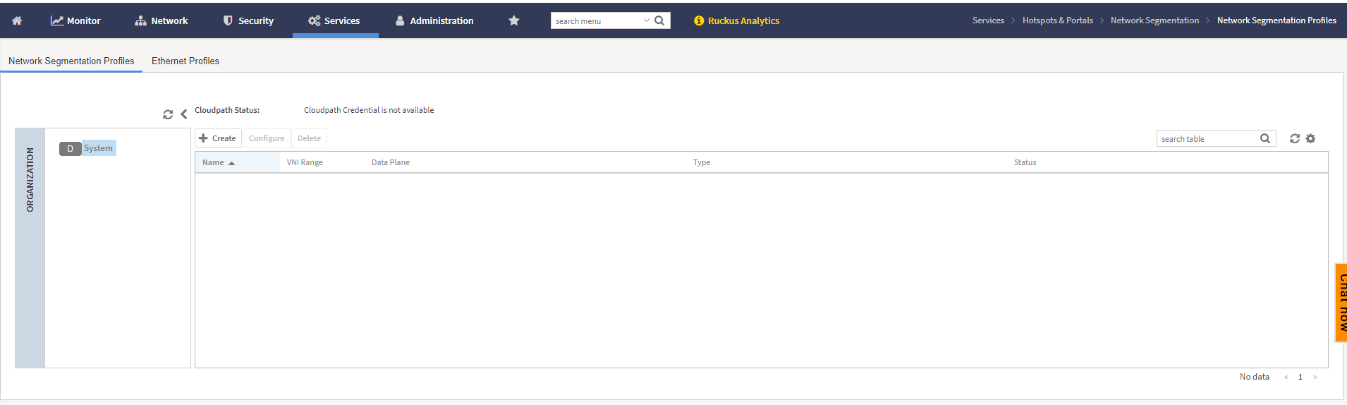
- On the menu, click to display the Network Segmentation Profiles.
- Click the
 icon to display the
Create Network Segmentation dialog
box.
icon to display the
Create Network Segmentation dialog
box.
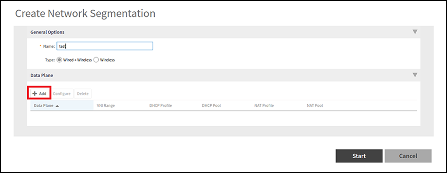
- Complete the following fields under the General
dialog box:
- Name: Enter a network segmentation profile name.
- Data
Plane: Select the data plane from the table or
create a data plane by clicking the
 icon to display the
Create Data Plane Relation
dialog box.
icon to display the
Create Data Plane Relation
dialog box.Complete the following fields:
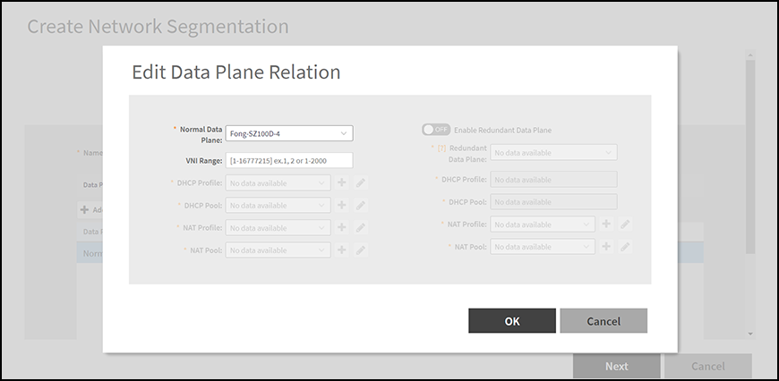
- Normal Data Plane: Select the data plane from the list.
- VIN Range: Enter the VNI range; ensure your VNI range is large enough to accommodate all units in the property. Each unit gets its own unique VNI.
- DHCP Profile: Select the DHCP profile from
the drop down list or click the
 to create a DHCP Profile.
refer to Creating Profile-based DHCP from the
RUCKUS Traffic Management Guide.
to create a DHCP Profile.
refer to Creating Profile-based DHCP from the
RUCKUS Traffic Management Guide. - DHCP Pool: Select the DHCP pool from the drop
down list or click the to create a DHCP pool.
Refer to Creating Profile-based DHCP from the
RUCKUS Traffic Management Guide.
- NAT Profile: Select the NAT profile from the
drop down list or click the to create a NAT profile.
Refer to Creating Profile-based NAT from the RUCKUS
Traffic Management Guide.
- NAT Pool: Select the NAT pool from the drop
down list or click the to create a NAT pool.
Refer to Creating Profile-based NAT from the RUCKUS
Traffic Management Guide.
- Click Next.
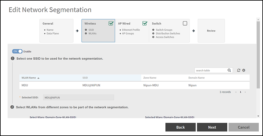
- Complete the following
fields under the Wireless dialog box:
By defaut, the Wireless option is disabled. Switch on to enable the Wireless option.
- Click Next.
- Complete the following
fields under the AP
Wired dialog box:
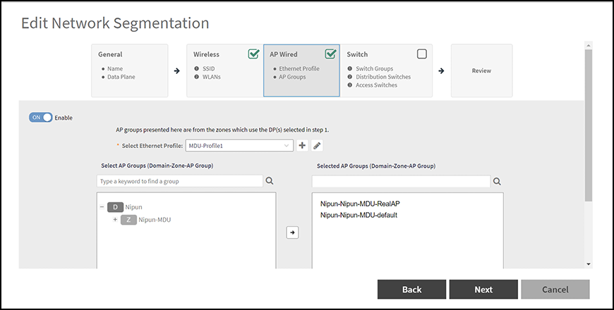
By defaut, the AP Wired option is disabled. Switch on to enable the AP Wired option.
- Select
the Ethernet profile: Select the ethernet profile
from the drop down list or click the icon to create an
ethernet profile.
Please provide information on creation of ethernet profile. I'm not able to enable the AP Wired feature.
The selected SSID will be displayed in the Selected SSID field.
- Select the AP group: Select the AP group from the table.
- Select
the Ethernet profile: Select the ethernet profile
from the drop down list or click the
- Click Next.
- Complete the following
fields under the Switch dialog box:
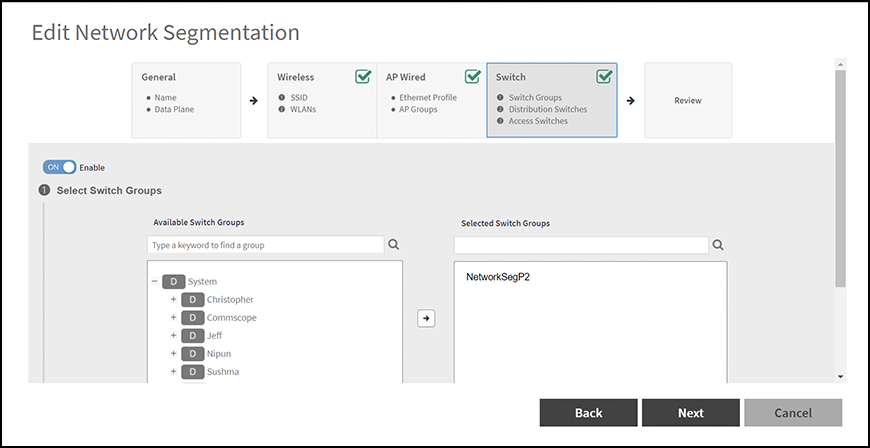
By defaut, the Switch option is disabled. Switch on to enable the Switch option.
- Select
the Switch Groups: From the table, select the switch
group which is to be added to the Network
Segmentation group.
Note: To select the participated Switch Group for the segment profile, administrator can utilize the search function to filter out the groups.
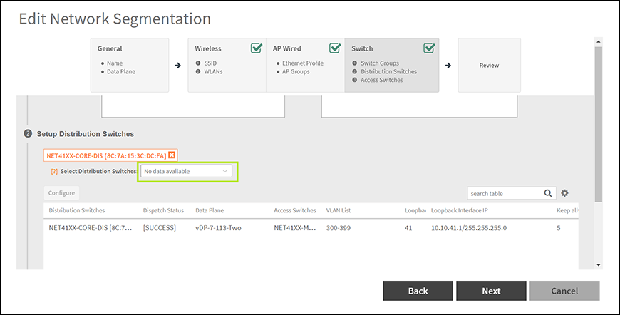
- Select
Distribution Switches: Select the distribution
switch from the drop down list which is to be added
to the Network Segmentation group.
Note: VXLAN is supported only on higher end switches such as ICX 7850, 7650 and 7550 model with router image, so distribution switch should use the above mentioned ICX models.
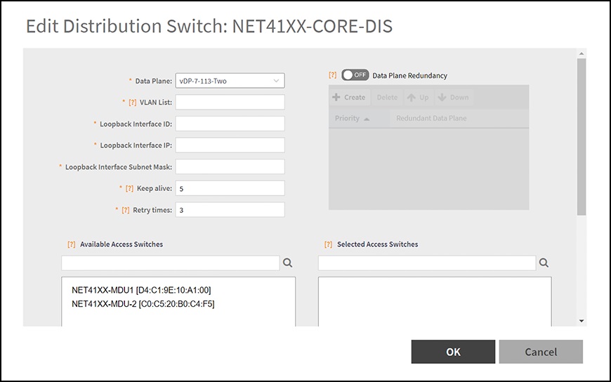
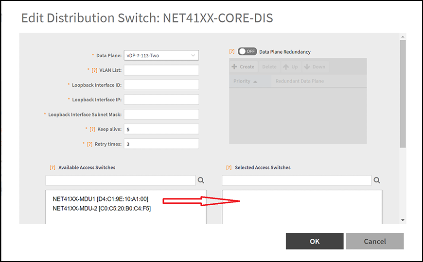
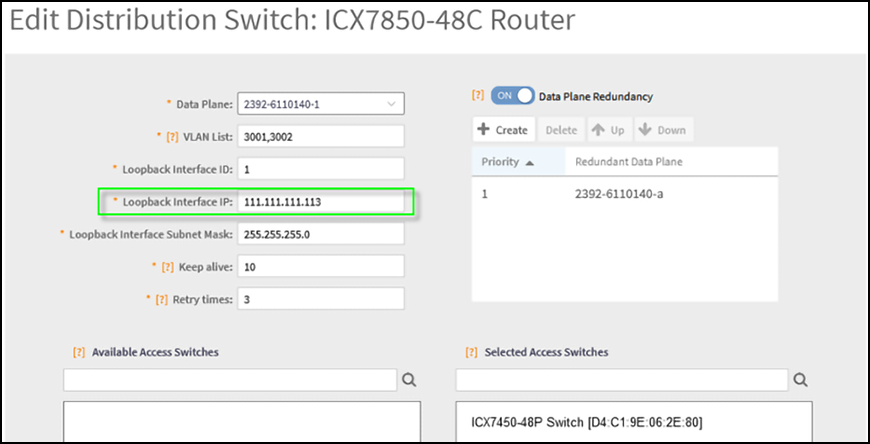
To configure the distribution switches, select the switch from the table and click Configure Icon to display the Edit Distribution Switch dialog box.
Complete the following fields:
- Data Plane: Select the data plane.
- VLAN List: Enter the VLAN List.
- Loopback Interface ID: Enter the Loopback Interface ID.
- Loopback Interface IP: Enter the Loopback Interface IP.
- Loopback Interface Subnet Mask: Enter the Loopback Interface Subnet Mask.
- Keep alive: Enter the keep alive time
interval to enable data plane monitor status. This
option is enabled, if the Data Plane Redundancy is switched
on.
Keep alive value is restricted between the range of 1 - 20 seconds to check Data plane status by ICMP Ping.
- Retry times: Enter the retry time interval
to enable data plane monitor status. This option
is enabled, if the Data Plane Redundancy is switched
on.
Retry times is restricted between the range of 1 - 5 to check Data plane status retry times if no response.
- Available Access Switches: The available access switches are displayed in the table.
- Selected Access Switches: Select the access switch from the interface.
- Data Plane Redundancy: Administrator can
disable/enable site redundancy.
Note: The maximum size of redundancy server is seven.
- Distribution Switch and Data Plane communicate
client VNI information via VxLAN Tunnel as
follows:
- Switch Client connect to Access Switch.
- Access Switch connect to the Distribution Switch.
- Distribution Switch establish VxLAN tunnel to the Data Plane.
- Distribution Switch use loopback interface connect to Data Plane interface.
- Network Routing will be carried out between Distribution Switch loopback interface and Data Plane data interface.
- Switch Client belonging to Access Switch should authenticate VLAN network.
- Browser will re-direct to Web Authentication page.
- After the Switch Client pass web authentication,
the Distribution Switch forward the client traffic
to Data Plane.
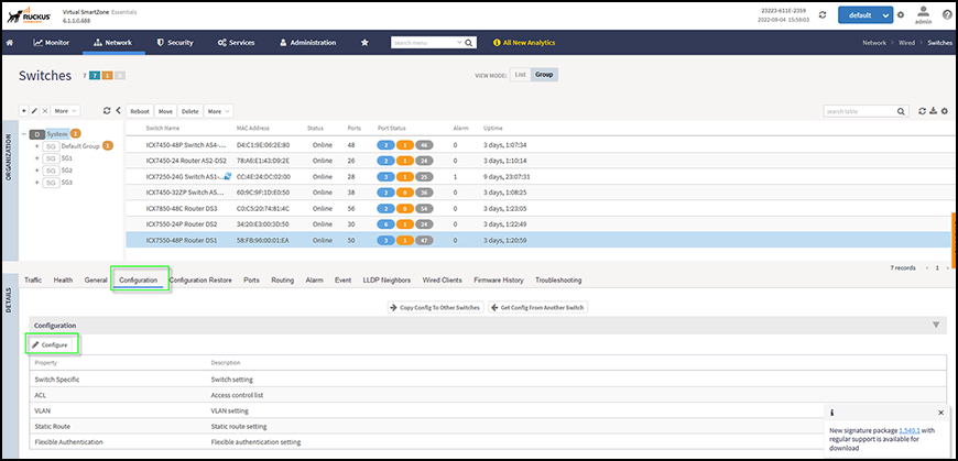
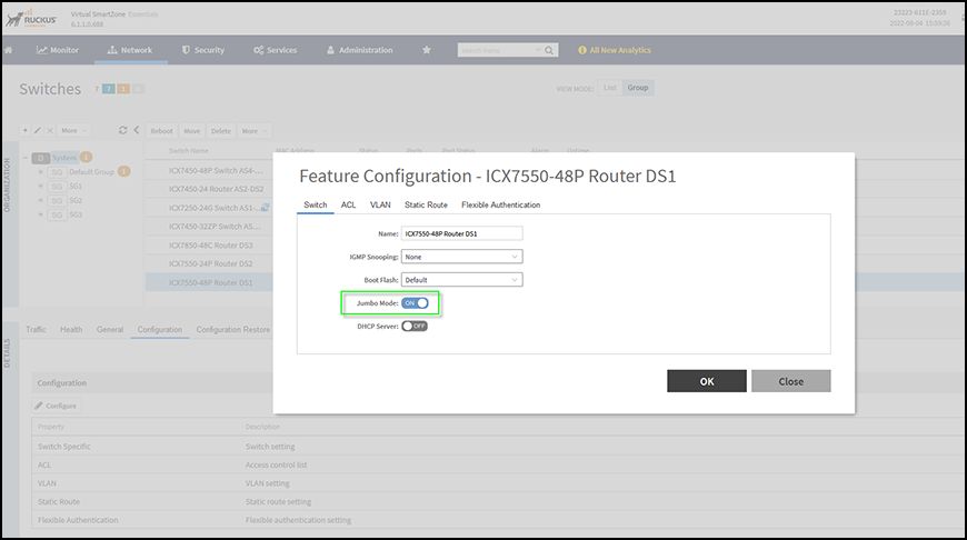
For the Network Segmentation function of Switch part, all devices between Distribution Switch and Data Plane must enable the Jumbo mode. This includes the Distribution Switch itself and vSZ-D Data interface which belongs to the vSwitch on ESXi. Otherwise, switch client will not be able to access the internet connection.
To enable the Jumbo mode, do the following:
- The data plane detects the VxLAN.
- Data Plane provide the DHCP/NAT service according to Switch Client VNI information.
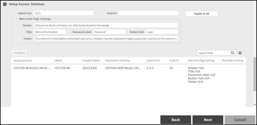
- Setup
Access Switches: Select the access switch and apply
the setting.
Complete the following fields:
- Select
the Switch Groups: From the table, select the switch
group which is to be added to the Network
Segmentation group.
- Click Next.
- Verify the data in the Review Page.
- Click OK.
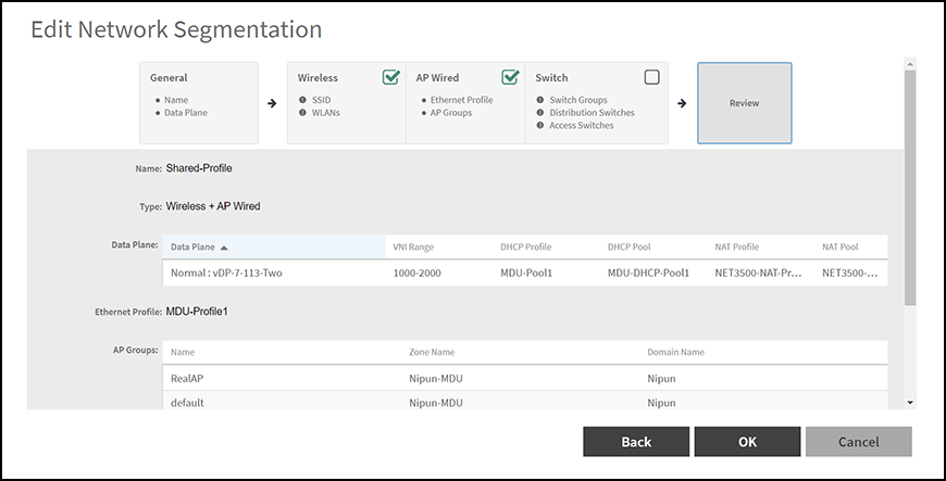
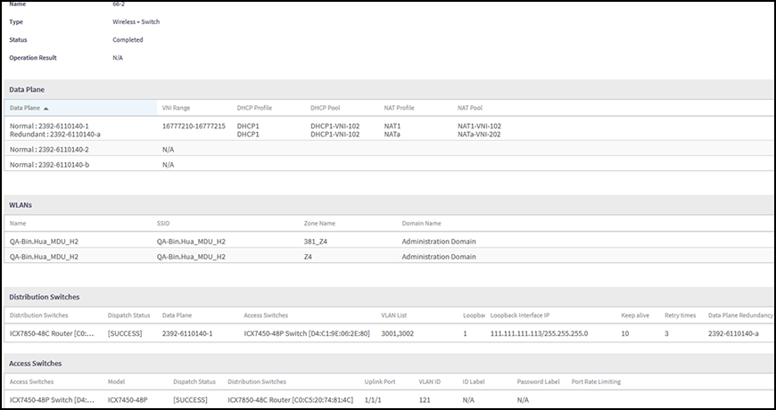
From the table, select the network segmentation profile to view the profile settings details.
Functions of switches are as follows:
- Access Switch provide Web Authentication Service and handles VLAN service.
- Distribution Switch
handles VNI/VLAN mapping and forward the traffic to Data Plane.
The data plane handles VNI and DHCP/NAT services.
When Switch Client access the internet by browser, most packets come back from gateway to the Data Plane. The Data Plane must add VxLAN header and then forward to the Distribution Switch.
Note: The maximum packet length between Distribution Switch and Data Plane is 1564 (1514 general +50 VxLAN header)