Layer 3 Multicast in an SPX Configuration
For multi-destination traffic, the CB sends a single copy of the packet for each VLAN to be replicated to the PE unit, while the PE unit performs local replication within the VLAN.
The following figure describes multicast traffic forwarding on Layer 3 devices.
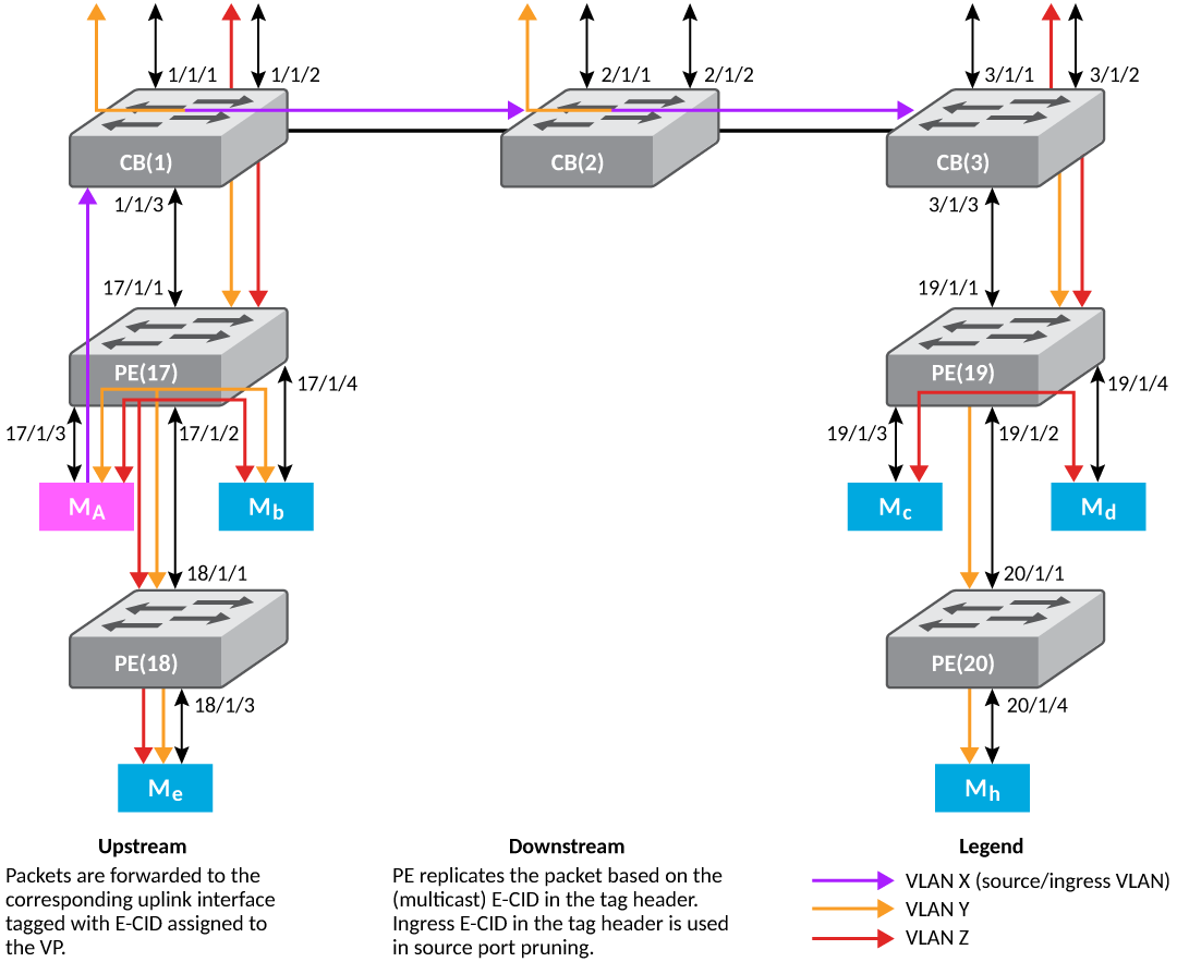
The following steps describe Layer 3 multicast forwarding in an SPX configuration:
- The Multicast E-CID Manager on the Control Bridge sets up the multicast E-CID forwarding path on the PE using Control and Status Protocol (CSP).
- A lookup is performed on the PE unit using the multicast E-CID in the E-Tag header.
- Multi-destination traffic sent by a CB on its cascade ports or LAGs is always VLAN tagged.
- The PE unit removes the VLAN tag while replicating the traffic on an untagged VLAN port.
- The PE unit can perform local replication within the VLAN.
- The CB sends a copy of the packet for each VLAN with multicast E-CIDs.
- The CB tracks inactivity of PIM mcache entries.
Layer 3 Multicast Scaling Numbers
The following table details the SPX stacking scaling numbers with IPv4 and IPv6 multicast snooping optimization turned on.
Multicast Scaling Numbers with Optimization Turned On
| System Parameter | Scaling Number |
|---|---|
| IGMP Groups | 8192 |
| PIMv4 Mcache | 6144 |
| MSDP Peers | 64 |
| MSDP SA cache | 8192 |
| MLD Groups | 8192 |
| PIMv6 Mcache | 2048 |
The following table details the SPX stacking scaling numbers with IPv4 and IPv6 multicast snooping optimization turned off. This is the default behavior.
- With PE ports being OIFs (receiver ports) and a maximum of 8 SPX ports on each CB unit. This number can be higher with a lesser number of SPX ports on each CB unit. ↩