Layer 2 Multicast in an SPX Configuration
In releases prior to FastIron 8.0.40, Layer 2 forwarding lookup occurred on the ingress packet process of the unit. With the introduction of SPX stacking, Layer 2 forwarding lookup for the traffic that ingresses on a PE port always occurs on the CB. For multi-destination traffic, the CB sends a single copy of the packet to the PE unit, while the PE unit takes care of local replication. The E-CID of the source PE port is carried in the E-Tag header (as the ingress E-CID) so that the source PE unit can perform source port pruning.
The following figure illustrates how multicast traffic forwarding occurs on Layer 2 devices.
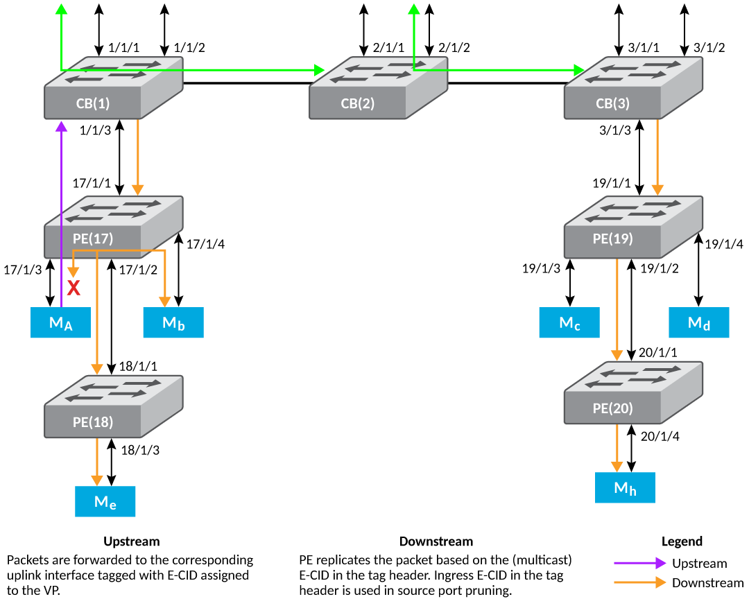
The following steps explain Layer 2 multicast forwarding:
- The Multicast E-CID Manager on the CB sets up the multicast E-CID forwarding path on the PE using the 802.1BR Control and Status Protocol (CSP).
- A lookup is performed on the PE unit using the multicast E-CID in the packet 802.1BR E-Tag header.
- Multi-destination traffic sent by the CB on its cascade ports or LAG ports is always VLAN tagged.
- The PE removes the VLAN tag while replicating the traffic on an untagged VLAN port.
Layer 2 Multicast Scaling Numbers
The following table lists the SPX stacking scaling numbers with IPv4 and IPv6 multicast snooping optimization turned on.
Layer 2 Multicast Scaling Numbers with Optimization Turned On
| System Parameter | Scaling Number |
|---|---|
| IGMP Groups | 8192 |
| IGMP Mcache | 8192 |
| MLD Groups | 8192 |
| MLD Mcache | 8192 |
The following table lists the SPX stacking scaling numbers with IPv4 and IPv6 multicast snooping optimization turned off. This is the default behavior.
- With PE ports being OIFs (receiver ports) and a maximum of 8 SPX ports on each CB unit. This number can be higher with a lesser number of SPX ports on each CB unit. ↩