Authenticating an IP phone using 802.1X
This use case shows the configuration required on a RUCKUS ICX device to authenticate an 802.1X-capable phone in a voice VLAN. In the following example, after authentication, the phone will be authenticated in voice VLAN 200.
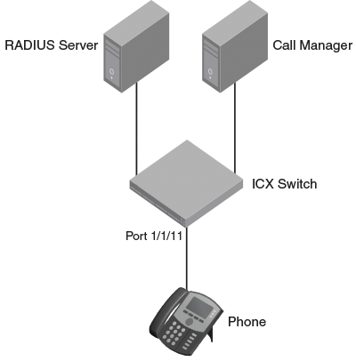
Create a profile for the phone on the RADIUS server, and configure the attributes in the following table.
RADIUS attributes for an IP phone
| Attribute | Value | Comment |
|---|---|---|
| Tunnel-Medium-Type | IEEE-802 | |
| Tunnel-Pvt-Group-ID | T:200 | The format is T:<Voice-VLAN-ID> |
| Tunnel-Type | VLAN | |
| Foundry-Voice-Phone-Config | " " | Dscp:46, priority:5 are LLDP advertised |
RUCKUS ICX switch configuration
- Specify RADIUS as an authentication server. The following command configures the switch
to use the configured RADIUS server to authenticate 802.1X authentication or MAC authentication
clients.
device(config)# aaa authentication dot1x default radius
- Configure a RADIUS server. In the following example, the RADIUS server IP address
is 10.20.64.208 and the shared key is "secret". The shared key must match the key
given during client configuration on the RADIUS server. UDP port 1812 is used for
RADIUS authentication messages, and UDP port 1813 is used for RADIUS accounting messages.
device(config)# radius-server host 10.20.64.208 auth-port 1812 acct-port 1813 default key secret dot1x mac-auth web-auth
- Create a VLAN to use as the auth-default VLAN. This VLAN must be configured to enable
authentication. When any port is enabled for 802.1X authentication or MAC authentication,
the port is moved into this VLAN by default as a MAC VLAN member. Sometimes the RADIUS
server may authenticate the client but not return VLAN information on where the client
should be placed. The auth-default VLAN is used in this scenario.
device(config)# vlan 2 name auth-default-vlan
device(config-vlan-2)# exit
- The authentication-enabled port must be a tagged member of the voice VLAN before
configuring LLDP. The virtual interface IP address of the voice VLAN will be used
as the gateway IP address for the phone. In this example, VLAN 200 is used as the
voice VLAN.
device(config)# vlan 200 name voice
device(config-vlan-200)# tagged ethernet 1/1/1
device(config-vlan-200)# router-interface ve 200
device(config-vlan-200)# exit
device(config)# interface ve 200
device(config-vif-200)# ip address 172.20.74.1/24
- Configure the IP helper on the virtual interface of the voice VLAN so that a DHCP
request from the IP phone is forwarded to the call manager. In the following steps,
the call manager IP address is 10.20.74.31.
device(config-vif-200)# ip helper-address 1 10.20.74.31
device(config-vif-200)# exit
- LLDP will be configured automatically if the Foundry-Voice-Phone-Config attribute
is configured in the RADIUS server. LLDP advertises the VLAN information so that the
client connected to the port learns the voice VLAN.
If the Foundry-Voice-Phone-Config attribute is not configured, configure LLDP manually to advertise VLAN 200 as the voice VLAN on port 1/1/11. An LLDP warning message will be shown to indicate that port 1/1/11 is not part of VLAN 200. This warning can be ignored because port 1/1/11 will be added to VLAN 200 by way of dynamic VLAN assignment after authentication.
device(config)# lldp run
device(config)# lldp med network-policy application voice tagged vlan 200 priority 5 dscp 46 ports ethernet 1/1/11
LLDP Warning: Network policy: Port 1/1/11 is not a member of VLAN 200
- Specify which VLAN ID to use as the auth-default VLAN under authentication mode. Refer
to Step 3 for the use of the auth-default VLAN.
device(config)# authentication
device(config-authen)# auth-default-vlan 2
- Enable 802.1X on the switch under authentication mode, and enable 802.1X on port 1/1/11.
Configure the port control mode as
auto in general configuration mode. This mode enables 802.1X authentication on the interface.
device(config)# authentication
device(config-authen)# dot1x enable
device(config-authen)# dot1x enable ethernet 1/1/11
device(config-authen)# exit
device(config)# dot1x port-control auto ethernet 1/1/11
- Enable PoE on port 1/1/11 using the
inline powercommand in interface configuration mode.device(config)# interface ethernet 1/1/11 device(config-if-e1000-1/1/11)# inline power device(config-if-e1000-1/1/11)# exit
- To verify the authentication-related configuration on the switch, use the
show run authenticationcommand. Authentication-related configurations are stored under the keyword "authentication".device# show run authentication authentication critical-vlan 601 auth-default-vlan 2 restricted-vlan 401 auth-fail-action restricted-vlan re-authentication dot1x enable dot1x enable ethe 1/1/11 dot1x guest-vlan 501 !