Viewing the Results of the Cable Analysis
show cable-diagnostics
                  					tdr
command to display the results of Virtual Cable Test (VCT) Time Domain Reflectometry
(TDR)
cable diagnostic testing. show cable-diagnostics
tdr command, including full descriptions of all output fields in the
command output, refer to the RUCKUS FastIron Command
Reference.In the following example, the command displays VCT TDR test results for port 15, slot 1 on device 1 in the stack, when the port is down the cable is not connected, or the cable or RJ-45 connector is defective. The results indicate that the speed of the link could not be determined (UNKWN). The test shows the status of each pair within the cable: Pair A has an open status, meaning there is no continuity; Pair B is terminated correctly with Pair A; Pair C is terminated with Pair D; and Pair D is terminated with Pair C. This setup suggests that while some pairs are correctly terminated, Pair A remains open, potentially indicating that the port is down, the cable is not connected, or the cable or RJ-45 connector is defective.
device# show cable-diagnostics tdr 1/1/15
Port      Speed    Local pair  Remote pair Pair status
--------- -----   ---------- ----------- -----------
1/1/15    UNKWN    Pair A                     Open
                   Pair B       Pair A        terminated
                   Pair C       Pair D        terminated
                   Pair D       Pair C        terminated
In the following example, the command displays VCT TDR test results for the same port when the port is active (UP). The test indicates that the port is operating at 1 Gigabit per second (1G). Each pair within the cable is shown with its corresponding remote pair and their termination status. In this case, all pairs (Pair A to Pair B, Pair B to Pair A, Pair C to Pair D, and Pair D to Pair C) are terminated. This termination status shows that there is a proper electrical connection between the pairs with consistent termination throughout the cable.
device# show cable-diagnostics tdr 1/1/15
Port      Speed Local pair  Remote pair Pair status
--------- ----- ---------- ----------- --------------
1/1/15     1G   Pair A       Pair B      terminated
                Pair B       Pair A      terminated
                Pair C       Pair D      terminated
                Pair D       Pair C      terminated
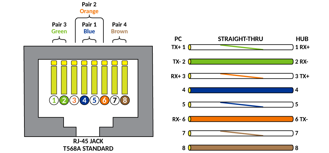
"Local pair" indicates the assignment of wire pairs from left to right, where Pair A is the left-most pair. The following table shows the Local pair mapping to the T568A pin/pair and color assignment from the TIA/EIA-568-B standard.
Local Pair Definition
|
Local Pair |
T568A Pair and Color Assignment |
|---|---|
|
Pair A |
Pair 3 (green) |
|
Pair B |
Pair 2 (orange) |
|
Pair C |
Pair 1 (blue) |
|
Pair D |
Pair 4 (brown) |
The following figure illustrates the T568A pin/pair assignment.