DHCP auto-provisioning on Layer 2 and Layer 3 devices
- If the non-default VLAN has multiple untagged ports connected to different DHCP servers, the first port that received the IP address offer will be considered and the other port will not receive an IP address. This behavior applies for default VLANs, too.
- After an image update and device reload, the option 3 (router) installs the default route to maintain the connectivity with the TFTP or DHCP servers. In releases prior to FastIron 8.0.40, option 3 was supported only on Layer 2 devices. The default route added by the DHCP client device from option 3 (router) will be of the lowest metric (254). If the device has a default route, the DHCP provided route is also appended to the routing table.
Differences between switch and router image DHCP clients
| Layer 2 DHCP client | Layer 3 DHCP client |
|---|---|
| IP address is configured on the switch (globally) | IP address is configured on the specific client port |
| IP default gateway is configured as “Default gateway X.X.X.X (option 3) | Default route is configured as “IP route” with distance metric 254 |
The following scenarios illustrate DHCP auto-provisioning in different environments.
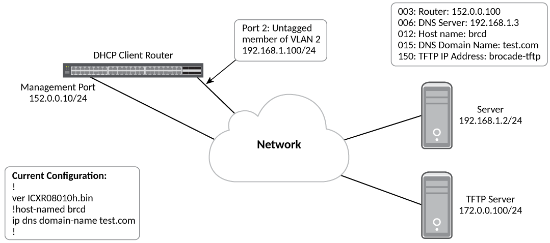
In this scenario, the DHCP client and server are part of the same network, but the TFTP server is part of a different network. Here the DHCP client device needs a default route for TFTP server reachability.
- The FastIron router (DHCP client) connected to the DHCP server is booted.
- The client obtains a dynamic IP address lease from the DHCP server through the untagged member port 2 of the VLAN 2 (which is a non-default VLAN) along with other DHCP server options.
- Once DHCP server options are enabled, the router option 3 is processed and installs the default route onto the device. Options 6,12, 15, and 150 are processed as well.
- If auto-provisioning is enabled and the image file comparison is successful, the client downloads the new image using the TFTP server IP address specified in the DHCP server.
- If auto-provisioning is enabled, the client downloads the configuration file after connecting to the TFTP server and applies the running configuration on the device.
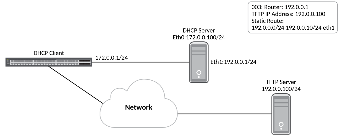
In this scenario, the DHCP client and server are connected in the same network, but the TFTP server is connected in a different network through the DHCP server. Here the DHCP client device needs a default route to reach the TFTP server. The steps are the same as in scenario 1, except that the TFTP server will be reachable after the new image update as the router option 3, which is the default gateway IP address 192.0.0.1, is installed.
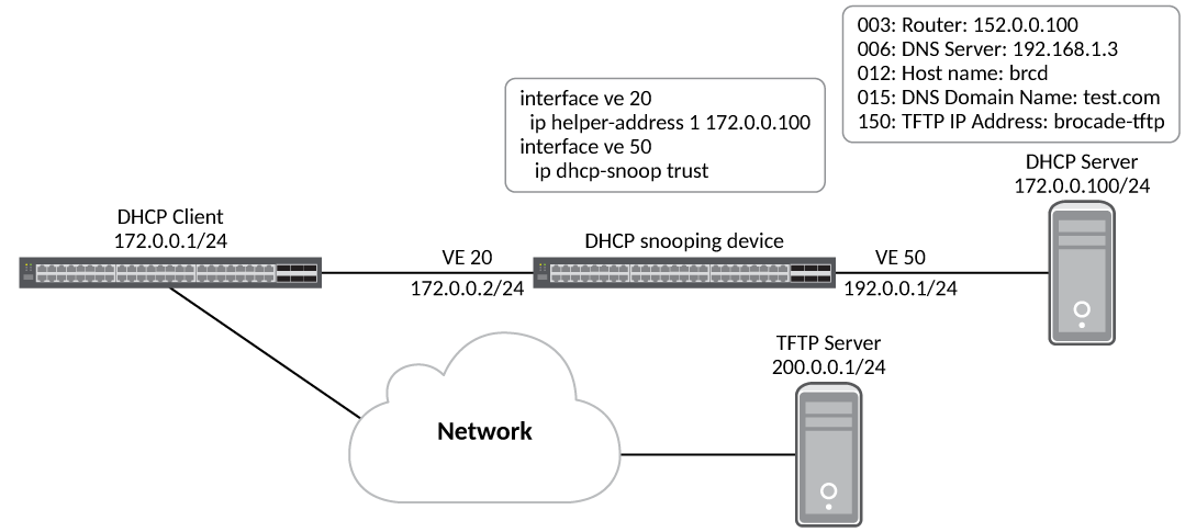
In this scenario, the DHCP client and server are connected through ports on which DHCP snooping or relay agent are enabled and are part of non-default VLANs. The working scenario is the same as Scenario 1.
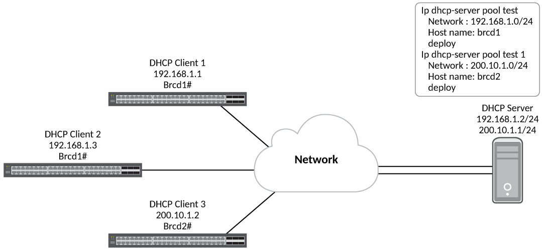
In this scenario, the DHCP clients 1 and 2 are connected to the DHCP server in the same subnet. Subsequently, both receive the same host name. The DHCP client 3 is connected to the DHCP server in a different subnet and it is assigned with the host name of the second pool.
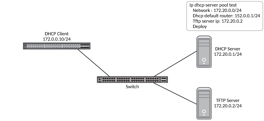
In this scenario, auto-provisioning on a Layer 2 device occurs as follows:
- The DHCP client device is powered on.
- The client sends the DHCP discovery packets on all DHCP client-eligible ports that are up.
- The client obtains the dynamic IP address from the DHCP server along with option 3.
- Once the new image is brought up, the client tries to connect to the TFTP server using the default route.