Convergence in a Complex IEEE 802.1w Topology
The following figure illustrates a complex IEEE 802.1w topology.
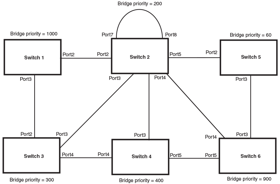
In the above figure, Switch 5 is selected as the root bridge since it is the bridge with the highest priority. Lines in the figure show the point-to-point connection to the bridges in the topology.
Switch 5 sends an RST BPDU that contains a proposal flag to Port5/Switch 2. When handshakes are completed in Switch 5, Port5/Switch 2 is selected as the Root port on Switch 2. All other ports on Switch 2 are given Designated port role with discarding states.
Port5/Switch 2 then sends an RST BPDU with an agreed flag to Switch 5 to confirm that it is the new Root port and the port enters a forwarding state. Port7 and Port8 are informed of the identity of the new Root port. The IEEE 802.1w algorithm selects Port7 as the Designated port while Port8 becomes the Backup port.
Port3/Switch 5 sends an RST BPDU to Port3/Switch 6 with a proposal flag. When Port3/Switch 5 receives the RST BPDU, handshake mechanisms select Port3 as the Root port of Switch 6. All other ports are given a Designated port role with discarding states. Port3/Switch 6 then sends an RST BPDU with an agreed flag to Port3/Switch 5 to confirm that it is the Root port. The Root port then goes into a forwarding state.
Now, Port4/Switch 6 receives RST BPDUs that are superior to what it can transmit; therefore, it is given the Alternate port role. The port remains in discarding state.
Port5/Switch 6 receives RST BPDUs that are inferior to what it can transmit. The port is then given a Designated port role.
Next, Switch 2 sends RST BPDUs with a proposal flag to Port3/Switch 4. Port3 becomes the Root port for the bridge; all other ports are given a Designated port role with discarding states. Port3/Switch 4 sends an RST BPDU with an agreed flag to Switch 2 to confirm that it is the new Root port. The port then goes into a forwarding state.
Now, Port4/Switch 4 receives an RST BPDU that is superior to what it can transmit. The port is then given an Alternate port role and remains in discarding state.
Likewise, Port5/Switch 4 receives an RST BPDU that is superior to what it can transmit. The port is also given an Alternate port role and remains in discarding state.
Port2/Switch 2 transmits an RST BPDU with a proposal flag to Port2/Switch 1. Port2/Switch 1 becomes the Root port. All other ports on Switch 1 are given Designated port roles with discarding states.
Port2/Switch 1 sends an RST BPDU with an agreed flag to Port2/Switch 2 and Port2/Switch 1 goes into a forwarding state.
Port3/Switch 1 receives an RST BPDUs that is inferior to what it can transmit; therefore, the port retains its Designated port role and goes into forwarding state only after the forward delay timer expires twice on that port while it is still in a Designated role.
Port3/Switch 2 sends an RST BPDU to Port3/Switch 3 that contains a proposal flag. Port3/Switch 3 becomes the Root port, while all other ports on Switch 3 are given Designated port roles and go into discarding states. Port3/Switch 3 sends an RST BPDU with an agreed flag to Port3/Switch 2 and Port3/Switch 3 goes into a forwarding state.
Now, Port2/Switch 3 receives an RST BPDUs that is superior to what it can transmit so that port is given an Alternate port state.
Port4/Switch 3 receives an RST BPDU that is inferior to what it can transmit; therefore, the port retains its Designated port role.
Ports on all the bridges in the topology with Designated port roles that received RST BPDUs with agreed flags go into forwarding states instantly. However, Designated ports that did not receive RST BPDUs with agreed flags must wait until the forward delay timer expires twice on those ports. Only then will these ports move into forwarding states.
The entire IEEE 802.1w topology converges in less than 300 msec and the essential connectivity is established between the designated ports and their connected root ports.
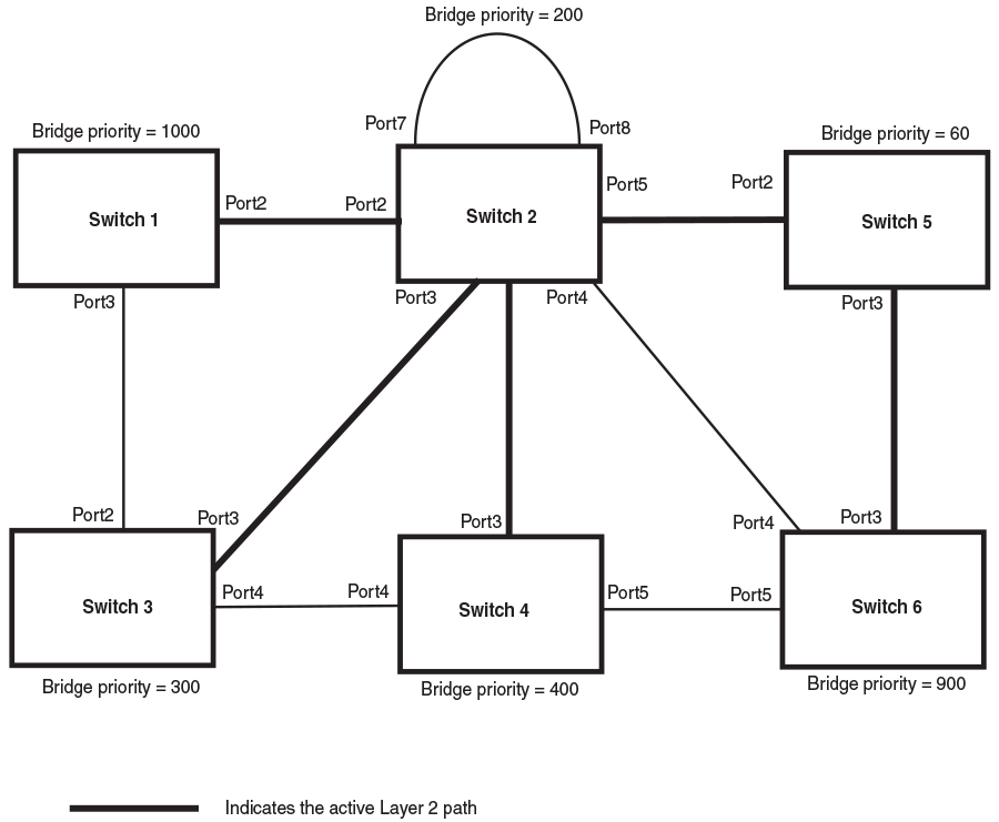
After convergence is complete, the following figure shows the active Layer 2 path of the topology.