Convergence after a Link Failure
The following figure illustrates a link failure in the IEEE 802.1w topology. In this example, Port2/Switch2, which is the port that connects Switch 2 to the root bridge (Switch 1), failed and both Switch 2 and Switch 1 are affected by the topology change.
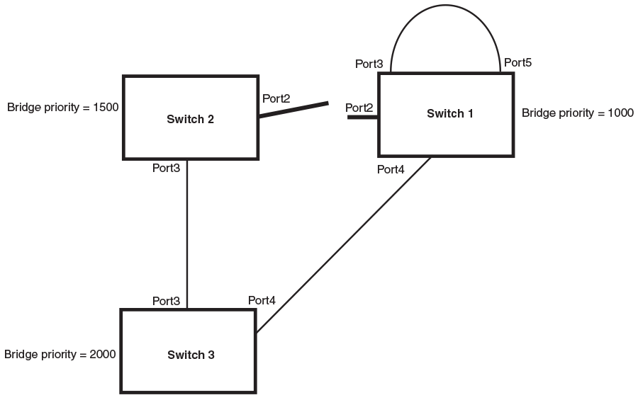
Switch 1 sets its Port2 into a discarding state.
At the same time, Switch 2 assumes the role of a root bridge since its root port failed and it has no operational Alternate port. Port3/Switch 2, which currently has a Designated port role, sends an RST BPDU to Switch 3. The RST BPDU contains a proposal flag and a bridge ID of Switch 2 as its root bridge ID.
When Port3/Switch 3 receives the RST BPDUs, the IEEE 802.1w algorithm determines that they are inferior to those that the port can transmit. Therefore, Port3/Switch 3 is given a new role, that of a Designated port. Port3/Switch 3 then sends an RST BPDU with a proposal flag to Switch 2, along with the new role information. However, the root bridge ID transmitted in the RST BPDU is still Switch 1.
When Port3/Switch 2 receives the RST BPDU, the IEEE 802.1w algorithm determines that it is superior to the RST BPDU that it can transmit; therefore, Port3/Switch 2 receives a new role; that of a Root port. Port3/Switch 2 then sends an RST BPDU with an agreed flag to Port3/Switch 3. Port3/Switch 2 goes into a forwarding state.
When Port3/Switch 3 receives the RST BPDU that Port3/Switch 2 sent, Port3/Switch 3 changes into a forwarding state, which then completes the full convergence of the topology.