802.1W Convergence in a Simple Topology
The examples in this section illustrate how 802.1W convergence occurs in a simple Layer 2 topology at start-up.
Convergence at Start Up
In the following figure, two bridges Switch 2 and Switch 3 are powered up. There are point-to-point connections between Port3/Switch 2 and Port3/Switch 3.
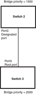
At power up, all ports on Switch 2 and Switch 3 assume Designated port roles and are at discarding states before they receive any RST BPDU.
Port3/Switch 2, with a Designated role, transmits an RST BPDU with a proposal flag to Port3/Switch 3. A port with a Designated role sends the proposal flag in its RST BPDU when they are ready to move to a forwarding state.
Port3/Switch 3, which starts with a role of Designated port, receives the RST BPDU and finds that it is superior to what it can transmit; therefore, Port3/Switch 3 assumes a new port role, that of a Root port. Port3/Switch 3 transmits an RST BPDU with an agreed flag back to Switch 2 and immediately goes into a forwarding state.
Port3/Switch 2 receives the RST BPDU from Port3/Switch 3 and immediately goes into a forwarding state.
Now 802.1W has fully converged between the two bridges, with Port3/Switch 3 as an operational root port in forwarding state and Port3/Switch 2 as an operational Designated port in forwarding state.
Next, Switch 1 is powered up. See the following figure.
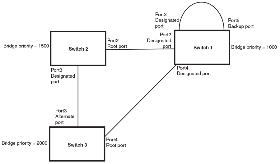
The point-to-point connections between the three bridges are as follows:
- Port2/Switch 1 and Port2/Switch 2
- Port4/Switch 1 and Port4/Switch 3
- Port3/Switch 2 and Port3/Switch 3
Ports 3 and 5 on Switch 1 are physically connected.
At start up, the ports on Switch 1 assume Designated port roles, which are in discarding state. The ports begin sending RST BPDUs with proposal flags. The flags indicate the ID of the bridge that the ports belong to, and the bridge that the ports understand to be the root bridge. The switch that eventually becomes the downstream neighbor is the only switch that sends a BPDU with the agreement bit set.
When Port4/Switch 3 receives these RST BPDUs 802.1W algorithm determines that they are better than the RST BPDUs that were previously received on Port3/Switch 3. Port4/Switch 3 is now selected as Root port. This new assignment signals Port3/Switch 3 to begin entering the discarding state and to assume an Alternate port role. As it goes through the transition, Port3/Switch 3 negotiates a new role and state with its peer port, Port3/Switch 2.
Port4/Switch 3 sends an RST BPDU with an agreed flag to Port4/Switch 1. Both ports go into forwarding states.
Port2/Switch 2 receives an RST BPDU. The 802.1W algorithm evaluates the BPDU and determines that it is superior to any BPDU that any other port on Switch 2 can transmit. Port2/Switch 2 assumes the role of a Root port.
The new Root port then signals all ports on the bridge to start synchronization. Since none of the ports are Edge ports, they all enter the discarding state and assume the role of Designated ports. Port3/Switch 2, which previously had a Designated role with a forwarding state, starts the discarding state. They also negotiate port roles and states with their peer ports. Port3/Switch 2 also sends an RST BPU to Port3/Switch 3 with a proposal flag to request permission go into a forwarding state.
The Port2/Switch 2 bridge also sends an RST BPDU with an agreed flag Port2/Switch 1 that Port2 is the new Root port. Both ports go into forwarding states.
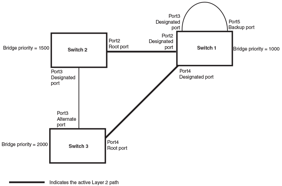
Now, Port3/Switch 3 is currently in a discarding state and is negotiating a port role. It received RST BPDUs from Port3/Switch 2. The 802.1W algorithm determines that the RST BPDUs Port3/Switch 3 received are superior to those it can transmit; however, they are not superior to those that are currently being received by the current Root port (Port4). Therefore, Port3 retains the role of Alternate port.
Ports 3/Switch 1 and Port5/Switch 1 are physically connected. Port5/Switch 1 received RST BPDUs that are superior to those received on Port3/Switch 1; therefore, Port5/Switch 1 is given the Backup port role while Port3 is given the Designated port role. Port3/Switch 1 does not go directly into a forwarding state. It waits until the forward delay time expires twice on that port before it can proceed to the forwarding state.
Once convergence is achieved, the active Layer 2 forwarding path converges as shown in the following figure.