Find Technical Content
  • Home
  • Ruckus Support Portal
  • Ruckus Networks
  • Table of Contents
  • Dark Mode

Powered by Titania Delivery

⚠ This cached page may be outdated. Click refresh to get the latest content.
Cached Version You are Offline

You are viewing a cached version of this page.

You are currently offline. This page was loaded from cache.

Multi-Chassis Trunking

  • 1 Multi-Chassis Trunking
    • 1.1 Multi-Chassis Trunking Overview
      • 1.1.1 How MCT Works
      • 1.1.2 MCT Terminology
      • 1.1.3 MCT Data Flow
      • 1.1.4 MCT and VLANs
      • 1.1.5 MCT Feature Interaction and Supported Features
      • 1.1.6 MCT Board Type Compatibility
    • 1.2 Basic MCT Configuration
      • 1.2.1 MCT Configuration Considerations
      • 1.2.2 MCT Recommendations and Best Practices
      • 1.2.3 Configuring MCT
        • 1.2.3.1 Step 1: Configure ICL for Cluster Devices and LAGs for Client Devices
        • 1.2.3.2 Step 2: Configure the MCT VLAN, MCT Session VLAN, Recommended MCT Keep-Alive VLAN, and ICL Forwarding Delay
        • 1.2.3.3 Step 3: Configuring the Cluster
        • 1.2.3.4 Step 4: Configuring Clients
      • 1.2.4 Forcing a Port Up in a Basic MCT Configuration
    • 1.3 Cluster Client Automatic Configuration
      • 1.3.1 Setting Up Cluster Client Automatic Configuration
    • 1.4 MCT Failover Scenarios
      • 1.4.1 Cluster Failover Mode
        • 1.4.1.1 Configuring the Failover Mode
      • 1.4.2 Client Isolation Mode
        • 1.4.2.1 Configuring Client Isolation Mode
      • 1.4.3 Shutting Down All Client Interfaces
      • 1.4.4 Using the Keep-Alive VLAN
      • 1.4.5 Setting Keep-Alive Timers and Hold Time
    • 1.5 MCT Hitless Upgrade
    • 1.6 Layer 2 Behavior with MCT
      • 1.6.1 Dynamic Trunks (LAGs)
      • 1.6.2 Port Loop Detection
      • 1.6.3 MCT Layer 2 Protocols
      • 1.6.4 Layer 2 Multicast Snooping over MCT
        • 1.6.4.1 IGMP and MLD Snooping
        • 1.6.4.2 IGMP and MLD Snooping Behavior on MCT Cluster Devices
        • 1.6.4.3 How Failovers are Handled for Layer 2 Multicast over MCT
        • 1.6.4.4 PIM-SM and PIM6-SM Snooping over MCT
        • 1.6.4.5 Forwarding Entries for PIM-SM and PIM6-SM Multicast Snooping
        • 1.6.4.6 Displaying Information for Multicast Snooping
        • 1.6.4.7 Multicast Snooping Configuration Example
    • 1.7 Layer 3 Behavior with MCT
      • 1.7.1 Layer 3 Unicast Forwarding over MCT
        • 1.7.1.1 Layer 3 Traffic Forwarding Toward MCT Clients
        • 1.7.1.2 Layer 3 Traffic Forwarding From MCT Clients
      • 1.7.2 User-defined VRF Support over MCT
      • 1.7.3 VRRP or VRRP-E over an MCT-Enabled Network
      • 1.7.4 OSPF and BGP over an MCT-Enabled Network
      • 1.7.5 Layer 3 with MCT Configuration Considerations
      • 1.7.6 MCT Configuration for a Single-Level MCT Deployment
        • 1.7.6.1 MCT Configuration: Router A
        • 1.7.6.2 MCT Configuration: Router B
        • 1.7.6.3 MCT Configuration: S1-SW Device
      • 1.7.7 MCT Configuration with VRRP-E
        • 1.7.7.1 VRRP-E Configuration: Router A
        • 1.7.7.2 VRRP-E Configuration: Router B
      • 1.7.8 MCT Configuration with OSPF
      • 1.7.9 MCT Configuration with BGP
      • 1.7.10 PIM Over MCT Intermediate Router Functionality
        • 1.7.10.1 MCT Peer as Intermediate Upstream Router
        • 1.7.10.2 MCT Peer as Intermediate Downstream Router
        • 1.7.10.3 Load Sharing of Multicast Traffic by MCT-Cluster on CCEP Links
        • 1.7.10.4 Fast Convergence of Multicast Traffic
        • 1.7.10.5 First Hop and Last Hop Router Support on MCT Cluster Devices for MCT VLANs
        • 1.7.10.6 RP Support on MCT Cluster Devices
        • 1.7.10.7 Anycast RP Support for MCT Cluster Devices
        • 1.7.10.8 Requirements for Multicast MCT
        • 1.7.10.9 Limitations
        • 1.7.10.10 Configuring Multicast Routing over MCT for IPv4
    • 1.8 Displaying MCT Information
      • 1.8.1 MAC Clear Commands
    • 1.9 Single-Level MCT Configuration Example
      • 1.9.1 Client 1 Configuration
      • 1.9.2 Client 2 Configuration
      • 1.9.3 AGG-A (R1) Configuration
      • 1.9.4 AGG-B (R2) Configuration
    • 1.10 Two-Level MCT Configuration Example
      • 1.10.1 AGG-A (R1) Configuration
      • 1.10.2 AGG-B (R2) Configuration
      • 1.10.3 DIST-A (R3) Configuration
      • 1.10.4 DIST-B (R4) Configuration
    • 1.11 MCT Configuration Example Using ICX 7850 Stacks as Cluster Peers
    • 1.12 MCT Hitless Sequential Upgrade

Single-Level MCT Configuration Example

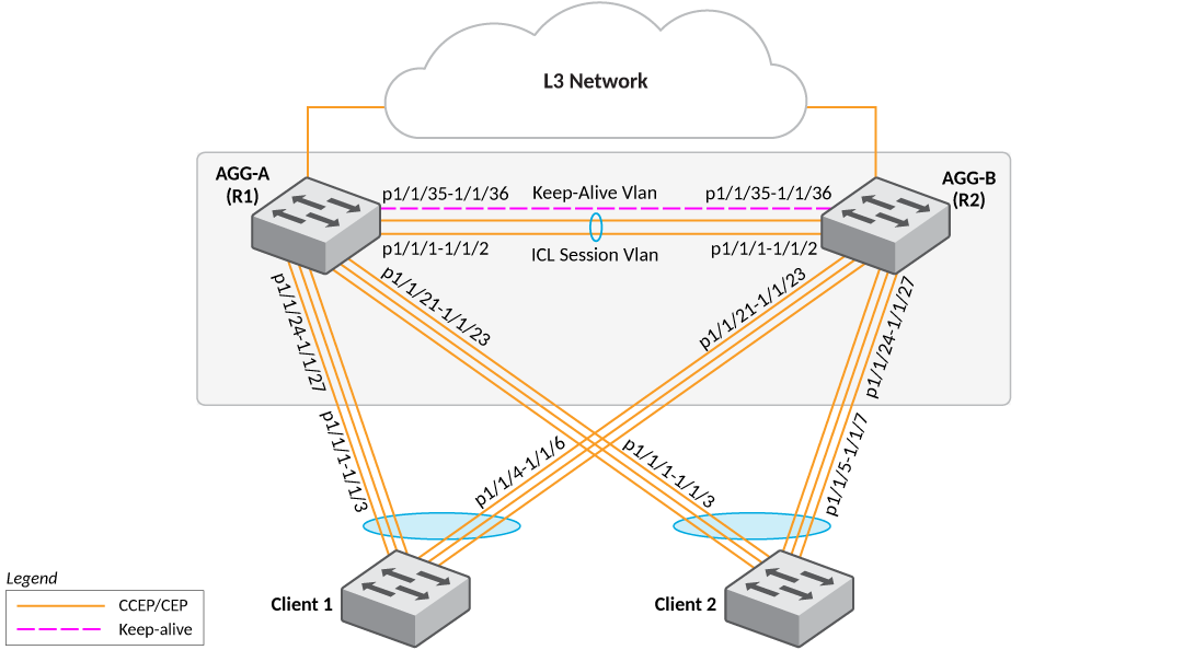
The following figure depicts a single-level MCT configuration. The clients can be server hosts or networking devices. The associated configuration follows.

Note: The LAG IDs are locally significant only and need not match on the two ends of a LAG.

Single-Level MCT Configuration

In this section:

  1. Client 1 Configuration
  2. Client 2 Configuration
  3. AGG-A (R1) Configuration
  4. AGG-B (R2) Configuration
Parent topic: Multi-Chassis Trunking

Did you find what you were looking for?
Thanks!

Ruckus Wireless

© 2026 Ruckus Wireless LLC All rights reserved.

  • Accessibility
  • Privacy & Cookies
  • Do Not Sell My Information
  • Trademarks
  • Terms
  • Feedback