Active-Active
As with active-standby, an active-active setup also has the concept of a primary node and secondary node. The primary node is the database server that is composed of initial data that will be replicated to the secondary database node during the replication setup. Be sure you know which node is your primary node before you proceed to configuration. If the cluster will contain application (APP) nodes, each such node must be added from the command line interface of its corresponding database node.
A load balancer is required for this topology. How to configure the load balancer is outside the scope of this manual. You can consult the documentation for the load balancer of your choice. Many open-source load balancers are available. Be sure to configure your load balancer with the information it needs about the nodes that will make up your cluster. When you configure the cluster, you are prompted to enter the virtual host name of the load balancer.
Network address translation (NAT):
Each type of active-active topology can be set up with or without NAT.
The following are the two basic types of active-active environments:
- Two database nodes that are instantaneously in sync once initial setup is complete. Refer to Active-Active Setup With Two Database Nodes Only.
- "Node groups" which consists of two database nodes that are also each connected via read/write access to one or more application nodes. Refer to Active-Active Setup With Two Node Groups.
Active-Active Setup With Two Database Nodes Only
This is the most basic type of active-active setup because it does not include any application nodes.
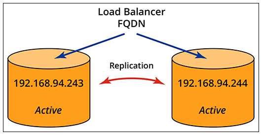
With this setup, both nodes simultaneously process enrollment requests and Radius AAA requests through the load balancer. If one node fails, the load balancer sends all requests to the other node.
Configuration of this cluster can be performed entirely from the primary node. To proceed, refer to:
Active-Active Setup With Two Node Groups
With an active-active setup, you have the flexibity of adding two application nodes to each of the two database nodes. One database node that also has one or more peer application nodes can be referred to as a node group, as shown in one possible configuration in the following illustration.
Cluster Using Node Groups
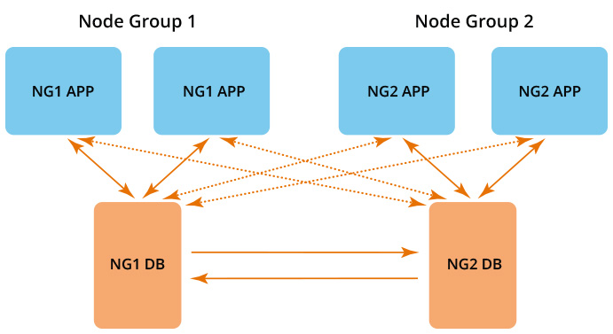
- Solid lines in the illustration denote read/write access between two nodes.
- Dashed lines in the illustration denote read/write access between an APP node and its secondary DB node, which only occues if its primary DB node is not available. A DB node is the primary DB server to its peer APP nodes in the same node group.
-
Note: A load balancer is required even thought the illustration above does not depict one.
Additional Node Group Information:
The following rules apply to how node groups are configured and behave within a cluster:
- APP node database reads/writes are proxied to both DB servers, with high priority to the DB server in the same node group.
- Each APP node enters the cluster through one DB node.
- The DB node manages cluster join/unjoin for its peer APP nodes.
- Each DB node is automatically also an APP node.
- All DB and APP nodes share the same cluster service name (domain name portion of enrollment portal URLs)
- No service downtime occurs on existing cluster nodes when an APP node is added/removed.
- Master-master DB asynchronous replication forms a shared database.
- Database nodes failover/failback to ensure shared database high availability.
- APP nodes failover/failback through the load balancer.
Configuration of a cluster that employs the use of node groups can be performed by referring to these topics:
Active-Active Setup for Two Data Centers
There are many ways to incorporate the use of a cluster. This is just another example topology of how you could set up two data centers that are located a great distance apart where you could implement two load balancers.
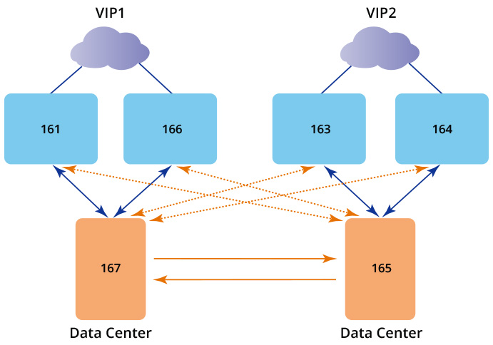
This scenario would exhibit the following behavior: