Ruckus Wired Campus Network Designs
There are four different design solutions that Ruckus recommends for building campus networks, depending on the network scale (as shown in Reference Designs).
Routed Access (Two/Three-Tier Model)
Stack Architecture (Two-Tier Model)
Two Cores with Multi-Chassis Trunking (MCT) and VRRP-E (Two/Three-Tier Model)
Campus Fabric (Two-Tier Model)
Reference Designs
Reference Designs |
<500 Ports |
500–3000 Ports |
>3000 Ports |
|---|---|---|---|
Routed Access |
No |
Yes |
Yes |
Stack (Core/Agg) |
Yes |
Yes |
Yes |
MCT |
No |
No |
Yes |
Campus Fabric |
Yes |
Yes |
No |
Routed Access (Two/Three-Tier Model)
The idea of placing multilayer switches in the access layer yields significant advantages simply because they can fully utilize all uplinks to the distribution layer (loops are no longer broken by the Spanning Tree Protocol (STP)). But most customer networks like to extend the Layer 3 architecture so that it is easier to implement for certain applications. In a routed access network, the Layer 3 virtual interfaces (VIs) are at the access layer. A hybrid Layer 2 and Layer 3 network can have both routed links as well as a Layer 2 access network by simply using the 802.1q (dot1q) trunking feature across these links flowing down to the access layer.
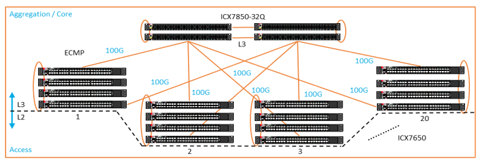
Equal cost multiple path (ECMP) can be implemented to maximize link utilization to the core
The design avoids Spanning Tree Protocol (STP) implementation complexity
Campus VLANs cannot be used between the access stacks
Complexity is increased on IP address management
There is an added cost to the premium licensing in the switch
VLANs cannot be re-used between stacks (Workaround would be to use VXLAN between stacks at the access layer to replicate VLANs)
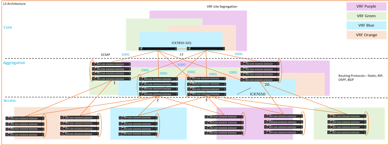
A variation of the routed access can be constructed by introducing VRFs at the core, distribution, and access layers to provide segmentation at the Layer 3 level. The core switches in this case can also be configured as Multi-Chassis Trunking (MCT) clusters to provide Layer 2 isolation. This hybrid design has proven to be successful in large customer enterprise networks.
Stack Architecture (Two-Tier Model)
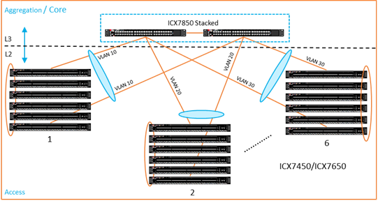
A stack is a group of devices that operate and are managed as a single entity. A Ruckus stack contains from 2 to 12 units configured in either a ring or a linear topology. The units in a stack are from the same model family; that is, a stack can be any of the Ruckus ICX 7000 series switches. Ruckus stackable devices are connected through ports that can be configured for either stacking or data. The location of stacking ports and the configuration options differ by device type.
In a stack architecture design, as shown in Stack Architecture, the uplinks from the access switch stacks are typically aggregated to form Link Aggregation Groups (LAGs). This increases the uplink capacity, as well as providing redundancy at the access layer.
Long distance stacking of up to 10 km is supported
Availability of In-Service Software Upgrade (ISSU)
A maximum of 12 ICX switches of the same model with different SKUs can be stacked together
There is an active controller and a standby controller for redundancy
The design provides for Layer 2 simplicity and fast failover
Two Cores with Multi-Chassis Trunking (MCT) and VRRP-E (Two/Three-Tier Model)
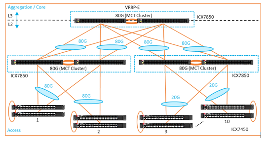
Multi-Chassis Trunking (MCT) can be used in a three-tier model. MCT is a technology that allows two MCT-supporting switches to cluster together and appear as a single logical device. Trunking is a technology that allows multiple links of a device to appear as one logical link. The combination of MCT and trunking allows for creating a resilient network topology that utilizes all links in the network, creating an ideal network topology for latency-sensitive applications. Dynamic LACP trunks provide link-level redundancy and increased capacity to the access layer.
VRRP-E is a Ruckus proprietary protocol that was designed to eliminate a single point of failure in a static default-route environment by dynamically assigning virtual IP routers to participating hosts. A virtual router is a collection of physical routers with interfaces that must belong to the same IP subnet. VRRP-E adds redundancy at the Layer 3 level. Each device in VRRP-E can be configured to route an upstream Layer 3 network, which essentially provides an efficient deployment.
MCT Cluster with VRRP-E illustrates an MCT design that can be deployed in enterprise networks as well as in certain data center scenarios. The MCT cluster can be formed using a pair of Ruckus ICX 7650, ICX 7750, or ICX 7850 switches. The MCT client stacks can be connected to the MCT pair subsequently. Dual links are used to provide redundancy as well as link aggregation.
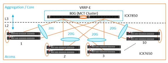
This design provides redundancy at the distribution layer with two Active-Active switches
Subsecond failover at the distribution layer
Flow-based load balancing
STP-free design
MCT clusters along with stacking is not supported
The maximum number of MCT clients supported is 50
LACP on ISL is not supported
GRE on the ISL VE interfaces is not supported
STP is not supported on MCT VLANs
IPv6 is not supported
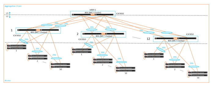
Ruckus has aggressively been testing a dual-layer model that can scale out the number of MCT clients. Scaled-Out Dual-Layer MCT Design shows a scaled-out design that can support up to 12 MCT client pairs, followed by 50 MCT clients to each MCT pair.
Campus Fabric (Two-Tier Model)
Campus Fabric creates a more scalable architecture based on the IEEE 802.1BR standards. The Ruckus Campus Fabric architecture shown in Campus Fabric can support Ruckus ICX 7750 or ICX 7650 switches as stack units that can be configured as Control Bridges (CBs) and the Ruckus ICX 7150, ICX 7250, and ICX 7450 switches as Port Extender (PE) units.
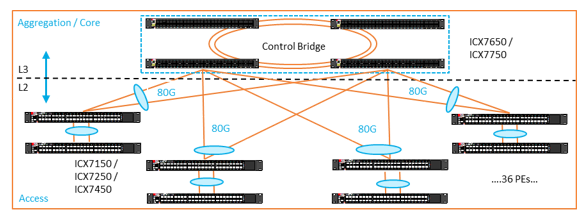
The Campus Fabric design can be used primarily as a two-tier model that is suitable for medium-sized campus networks where the core and distribution layers can be collapsed into a single layer. The Campus Fabric domain can contain from 1 to 4 CB units. A maximum of 36 PE units can be supported in a domain. Assuming there are 48 ports in each device, the domain can support up to 1800 ports.
Campus Fabric supports a distributed architecture as opposed to a bulky chassis architecture
Seamless mobility with Layer 3 boundaries between physical locations
Redundancy at the Control Bridge, aggregation, and core levels is available